- Joined
- Jan 1, 2014
- Messages
- 233
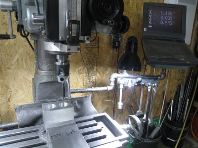
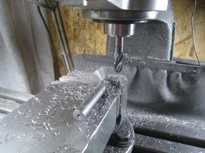
Last August I read an article from a June 1946 Science & Mechanics magazine published in Chicago Ill. on a 32.5cc engine by Model Craft. No drawings or castings are available but there was enough data to do a build from bar stock.
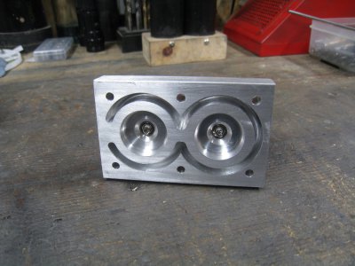
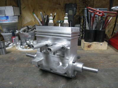
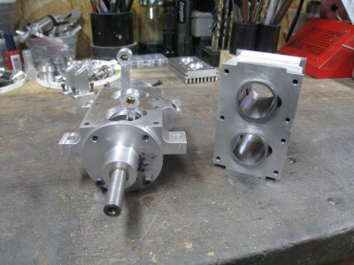
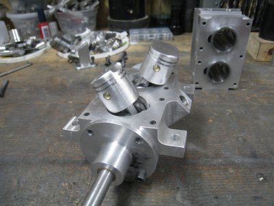
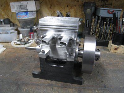
General specs - 2 cycle, 2 cylinder in line, 180 degree crank, water cooled, spark ignition, 1-1/8” bore and 1” stroke, central rotary intake valve.
Decided to go for it.
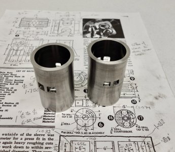
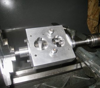
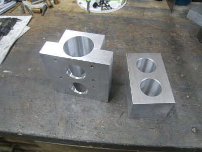
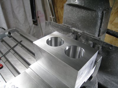
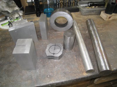
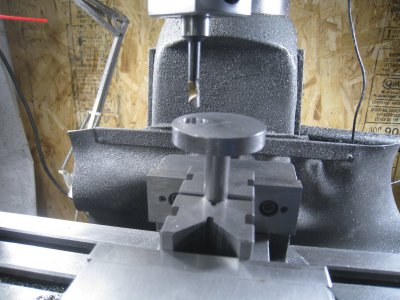
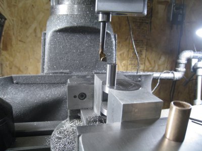
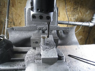
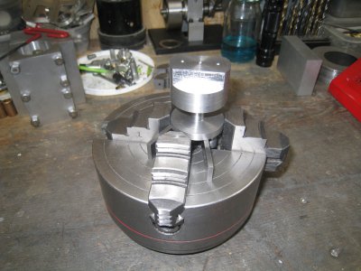
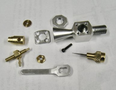
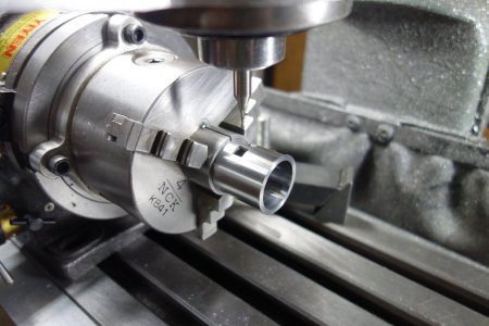
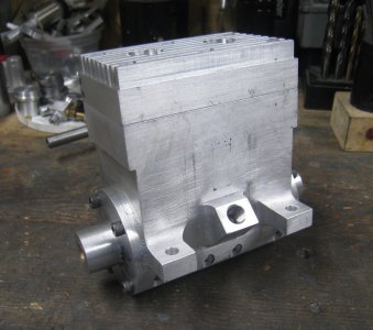
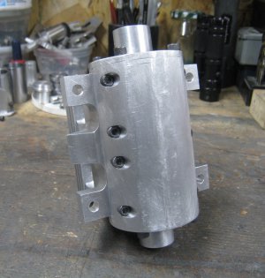
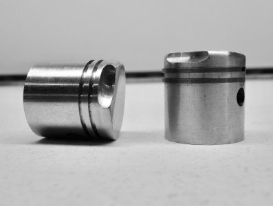
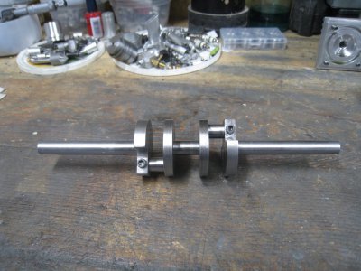
Used 1144 for the crank, 7075 for the pistons and rods, C12L14 for the sleeves, CI for the rings and rotary valve, CRS for the flywheel and 6061 for everything else. Bronze bushings are used in the rods and for the outer crankshaft bearings.
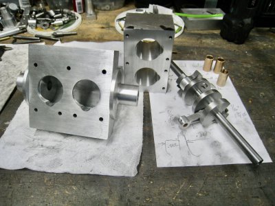
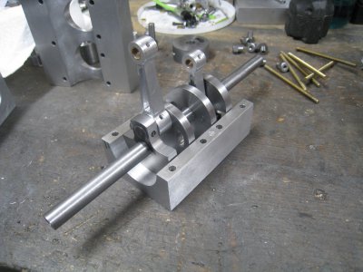
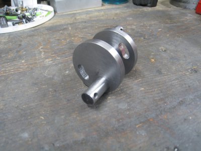
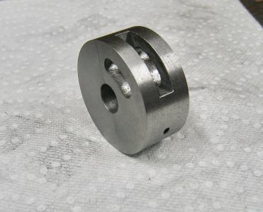
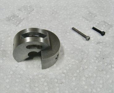
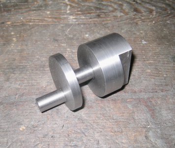
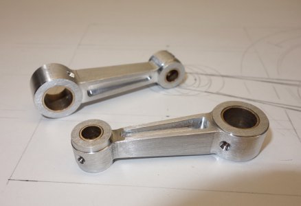
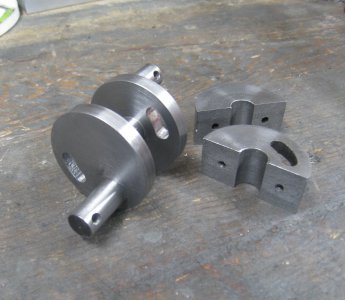
The article has 2 piece rods but the pictures clearly show a 3 piece crank which would not be necessary with split rods. I can only guess that they must have experimented with both 1 and 3 piece cranks. Anyways, I decided on the 3 piece crank and use 1 piece rods which enables a much tighter crankcase for better pumping action. The split centre CI rotary valve is 3/4” wide X 1-3/4” OD and serves as the centre bearing. The crankshaft centre section is made up of the centre bearing journal, 2 webs and the rod journals, and is a snug fit on the rotary valve, the end result is extremely rigid. The front and rear crank pieces just clamp unto the the rod journal ends and don’t really add to crank stiffness.
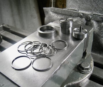
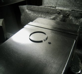
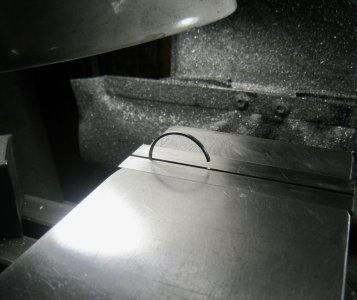
I read lots of opinions and ideas for rings and decided to turn them in cold form. Used 15% of the bore diameter to get the expanded ring gap of .168” giving a new ring OD of 1.179” and a ID of 1.084”. Once turned the extra circumference was removed by chisel and the ends filed square to be a able to just fit back into a clamping jig at bore size plus .001”. It was then skinned to bore size with no gap. Opinions are that it will have an adequate gap after the first run.
I borrowed the ignition system and fuel tank from my Boxer engine to ease the cost. The carburetor is of simple design with needle valve and barrel throttle and a 5/32” venturi which seems to be adequate for the engine size.
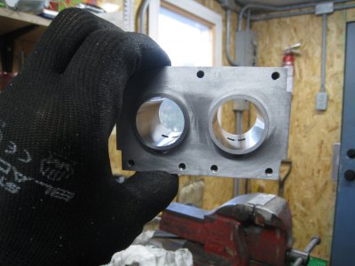
A water jacket of sorts was milled into the block and head and I planned to just use a gravity flow (bucket to bucket) but it doesn’t seem to get more than just warm in 3 minute runs. While this doesn’t sound very professional I don’t have room to display completed engines so the extra work of a radiator and water pump are kind of not warranted - hope no one takes offense.
Am using 80/20 methyl hydrate to castor oil. It started fairly easy and have 30+ minutes of run time so far. Have also used 50-1 chainsaw mix which runs about the same but with a lot less needle valve - must be thinner! Interestingly the ignition timing and mixture have a larger effect on engine speed than the throttle, so will need to play with it to see what works best. Compression certainly feels good and tested 49 and 54 lbs, might change the rings on the low cylinder to see if it improves.
In general it runs well and was shop time well spent!
Thanks for looking.
P.S. Will post the pictures in a couple of groups and a video separately.
General specs - 2 cycle, 2 cylinder in line, 180 degree crank, water cooled, spark ignition, 1-1/8” bore and 1” stroke, central rotary intake valve.
Decided to go for it.
Used 1144 for the crank, 7075 for the pistons and rods, C12L14 for the sleeves, CI for the rings and rotary valve, CRS for the flywheel and 6061 for everything else. Bronze bushings are used in the rods and for the outer crankshaft bearings.
The article has 2 piece rods but the pictures clearly show a 3 piece crank which would not be necessary with split rods. I can only guess that they must have experimented with both 1 and 3 piece cranks. Anyways, I decided on the 3 piece crank and use 1 piece rods which enables a much tighter crankcase for better pumping action. The split centre CI rotary valve is 3/4” wide X 1-3/4” OD and serves as the centre bearing. The crankshaft centre section is made up of the centre bearing journal, 2 webs and the rod journals, and is a snug fit on the rotary valve, the end result is extremely rigid. The front and rear crank pieces just clamp unto the the rod journal ends and don’t really add to crank stiffness.
I read lots of opinions and ideas for rings and decided to turn them in cold form. Used 15% of the bore diameter to get the expanded ring gap of .168” giving a new ring OD of 1.179” and a ID of 1.084”. Once turned the extra circumference was removed by chisel and the ends filed square to be a able to just fit back into a clamping jig at bore size plus .001”. It was then skinned to bore size with no gap. Opinions are that it will have an adequate gap after the first run.
I borrowed the ignition system and fuel tank from my Boxer engine to ease the cost. The carburetor is of simple design with needle valve and barrel throttle and a 5/32” venturi which seems to be adequate for the engine size.
A water jacket of sorts was milled into the block and head and I planned to just use a gravity flow (bucket to bucket) but it doesn’t seem to get more than just warm in 3 minute runs. While this doesn’t sound very professional I don’t have room to display completed engines so the extra work of a radiator and water pump are kind of not warranted - hope no one takes offense.
Am using 80/20 methyl hydrate to castor oil. It started fairly easy and have 30+ minutes of run time so far. Have also used 50-1 chainsaw mix which runs about the same but with a lot less needle valve - must be thinner! Interestingly the ignition timing and mixture have a larger effect on engine speed than the throttle, so will need to play with it to see what works best. Compression certainly feels good and tested 49 and 54 lbs, might change the rings on the low cylinder to see if it improves.
In general it runs well and was shop time well spent!
Thanks for looking.
P.S. Will post the pictures in a couple of groups and a video separately.
Attachments
-
 IMG_0363.jpeg337.2 KB · Views: 18
 -
 DSC07937.jpeg239.2 KB · Views: 14
 -
 IMG_0231.jpeg316.7 KB · Views: 14
 -
 DSC07952.jpeg371.7 KB · Views: 15
 -
 IMG_0295.jpeg410.6 KB · Views: 17
 -
 IMG_0305.jpeg362 KB · Views: 15
 -
 IMG_0315.jpeg309.1 KB · Views: 13
 -
 IMG_0325.jpeg425.4 KB · Views: 12
 -
 IMG_0330.jpeg441.4 KB · Views: 13
 -
 IMG_0331.jpeg335.6 KB · Views: 14
 -
 DSC07958.jpeg255.4 KB · Views: 13
 -
 IMG_0336.jpeg425.1 KB · Views: 14
 -
 IMG_0340.jpeg460.6 KB · Views: 13
 -
 IMG_0345.jpeg428.8 KB · Views: 14
Last edited: