

- Joined
- Oct 30, 2019
- Messages
- 197
This post is written mostly like my other "today I did" posts, but with content emphasizing/capturing information here that I wish other people captured when they posted online about their Harrison 10AA or Colchester Chipmaster oil leaks. Too many posts asked questions, eventually solved their problem, but never came back to share. Or they were mailing list threads with no pictures, etc.
Quick notes for future people coming from Google:
- Here is a version of the Colchester Chipmaster manual on the Internet Archive: https://ia601004.us.archive.org/34/items/lathe-manuals/Colchester Chipmaster Manual.pdf
- Also attached here
- This post is about oil leaks out of the headstock through/along the input shaft to the headstock gearbox
- The back cover to access the inside of the gearbox does not need to be opened/removed
- The front cover that covers the brake housing and brake disk does not need to be opened/removed
- Two seals should be replaced at the same time while the shaft is apart, details below along with theories on leaks from which seal will show up where; however this probably isn't worth differentiating
- One of these seals is very difficult to find for purchase, the larger one measuring 1-5/8 ID x 2-3/16 OD x 5/16 width. Either this seal needs to be located for purchase, or the spindle casting needs to be bored out to a larger diameter. Don't have a second lathe? Private message me, I may be able to help modify yours and send it back with the new seal installed.
The smaller seal is: 1" ID, 1-3/4" OD, 1/4" thick. Plenty of replacements available such as the DDS IN25.444.456.35SC: https://www.zoro.com/dds-shaft-seal...544445635sc/i/G500476890/?q=IN25.444.456.35SC $12.61 and in-stock at the time of writing
The larger one is hard to find: 1-5/8 ID x 2-3/16 OD x 5/16" thick. Thickness is not critical, you definitely could use something thinner, or at least as thick as 3/8 or 7/16. 1/2" could be pushing it, if that pushes the lip too close to the end of the feature that goes through this seal.
With the seal's seat bored out (details below) a cheap 2-1/4" OD seal such as SKF 16062 ($8 when I bought it)
--
In January 2020 I saw a lathe pop on Craigslist, which is rare for my area. I had just picked up my Logan 200 from near my hometown 6 hours from here a few months earlier, but figured I should jump on the opportunity to pick up a larger lathe locally.
Long story short, I got what I thought (and still think) was a good deal on the lathe and some accessories (steady rest, OEM followrest, OEM 5-tool capistan/turret, OEM hydraulic tracer unit, faceplate, 3- and 4-jaw chuck). The seller ended up including probably 500lbs of scrap/off-cuts as well, since I had asked how he came across that around our area, etc. The seller included the accessories (that he was originally going to sell separately), because this lathe turned out to have a much more significant oil leak than he had previously thought.

I got it home, filled it with oil, used it for about 15 minutes. 3-5 days later, all the oil from the headstock was in a puddle on the floor. All the shafts and belts that protrude from the rear of the headstock were coated in a sheen of oil, with oil running down most of the parts too. It was impossible to tell where the oil came from, since it slings all over the other parts when the machine is running (and runs out to the floor when resting)

Summer of 2020 I did a little bit of investigation, and ordered seals that were in the manual's parts list. One of them was easy to find a replacement for based on the dimensions in the parts index of the manual. However, the other one was difficult to find. Metal-housed, 1-5/8ID x 2-3/16 OD x 5/16 width. After some time looking, the only thing I could find was an expensive seal that didn't have a metal housing, was the correct ID and OD, and 3/8 width (not a critical dimension). I made a brief attempt at disassembling the clutch and input shaft assemblies early that fall, but it rapidly got more-involved than I was prepared to tackle at that time.
Fast forward to January 2023 after 3 years of this lathe not being used since I would fight an Exxon Valdez oil slick every time... I reached out to jwmelvin to see if he wanted to partner up and help me tackle this repair, finally. He was onboard, and 2 weekends ago we dove into it.
Before disassembling, you can see the red-painted casting that is coated in thinned-out gray grease. A previous owner put a molybdenum grease in the bearings on the input shaft. The oil leaks in question were thinning out that oil, which would sling out and coat everything nearby - like that casting, the belts, and the inside of the rear cover.

Here are some detailed notes for anyone who comes in from Google in the future. I am using a mix of names that helped me remember/write this down, but where possible I will reference ("in parentheses") the number and name of the part from the manual (attached):


First the cap ("1232 Washer") at the back of the clutch/rod ("1183 rod") assembly needs to be removed. This is retained by a nylock nut, but the end of the shaft actually has a taper that engages the retaining plate
1) Loosen but do not remove the 5/16 nylock nut ("1115 Rod Nut" but the back one) from the back of the input shaft
2) Remove the 3x flat-head machine screws (1/8 hex key drive)
3) Shift the clutch as if you are engaging the spindle
4) Hit the nylock nut with a soft-faced hammer until the taper breaks loose
5) Move the clutch lever back to the neutral position
6) Remove the nylock nut and cap/1232 Washer
7) Remove the "1275 Operating Collar"
Next remove the large snapring ("1277 Circlip-2"). The exact stack-up of parts retained by this seems to vary by the revision of the lathe. Mine does not exactly match that stack-up show in the manual page COM-16 7008.
Here is the snapring in question:

Generally this retains the hub components, cams/rollers ("1276 Bearing assembly") adjustment components ("1270 adjusting nut" or similar), and thrust components that bear against the clutch pack when the rod pulls the whole assembly towards the bed. Take pictures as you remove these since the manual copies online may not exactly match your machine's assembly, and try to keep them in order.
WARNING: the 3 rollers that move up ramps to engage the clutch are actually very small needle bearings. They will probably fall out after the thrust ring is removed, be ready. If they hit the ground, they will probably fall apart and the 8 rolling elements will disappear.
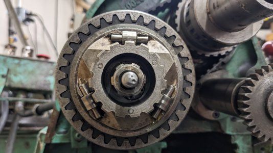
Slide these pieces out until you get to the the first clutch steel ("1268 Spinning plate").
Here is the stack-up after most of the outer pieces are removed (the "lock ring" is still in front of the first clutch steel)

Locate the snapring inside the hub, if yours is a design that has this. This snapring, if present, should retain the "1166 Pulley". Here is a picture showing the snap ring inside the hub. In my case the 3 rollers are stuck in with grease, this picture was actually during reassembly since it came out better than another one showing the same thing.

Remove the snapring and remaining/entire pulley assembly, which has 2 bearings inside. This may require some persuasion since the bearings are a light press fit onto their journals on the splined shaft, but only gentle taps distributed around the pulley assembly since that force will translate through the rolling elements of the bearings.
Your shaft should now look like this:

The seal shown/visible ("1133 Plate Oilseal") is one of the two, the one that can actually be bought reasonably easily.
Remove the the 6x flat-head screws ("1187 Plate Screw").
Pull the plate ("1149 plate c/w brgs") off the shaft. This has 2 needle bearings inside, has a register that sits inside the pulley ("1171 pulley"), and also protrudes through the second seal. You may need to pursuade this with a soft-faced hammer, at least for the first ~1/4" of its movement. For me the needle bearings inside were caged or otherwise did not have their rolling elements fall out, but I can't guarantee if that is the case for everyone.
The seal in this part is replaced just by prying it out with a prybar, and pressing the new one in - nothing special.
Slide the timing belt off. If you pull sideways on it and rotate the spindle manually, you can gradually walk it off.
If you look inside the pulley ("1171 pulley") on the shaft, you should see a large snapring. It may be buried in grease. Remove the snapring, and pull the pulley off. The pulley has a large bearing in it and may resist sliding off at first.
Now you should be left with the bare spindle protruding off the machine, all parts have been removed off it:

This spindle has the second seal pressed into it from the back. The spindle is a cast iron piece ("1093 Clutch Housing") retained by 5 or 6 screws ("1188 Housing Screw"). Mine only had 5, because there is a flat feature on my spindle casting where the flange is reduced and no 6th screw exists. This casting may be sealed to the headstock with sealant, I don't know what would be there from the factory. Mine was sealed on with RTV, so I needed to use a sharpened putty knife (or destroyed wood chisel) with a hammer to break it lose. Be careful, the back of the casting is not flat, it has a round register protruding that aligns it in the headstock.
Once removed, clean this up and observe the back. Here is mine, with the original seal still installed:

This is where things get a bit challenging:
- The seal that is installed should be a metal-housed seal, pressed into the 2.1875 bore (towards the face it probably is ~2.250, but there is a step where it reduces further). This is challenging to remove, and will be destructive to the seal - so have your new one available first. Here is the process that eventually worked for us. Unfortunately we were 100% in problem-solving mode and took no pictures
1) Place the spindle casting in a vise with soft jaws, clamping lightly on the first boss on the spindle side. It does not really need to clamp, this is just to hold it still. Do not clamp on the polished surface, as that is a bearing journal
2) Use an awl or sacrificial screwdriver/etc sharpened to a point on a bench grinder, with a hammer, to drive the awl down behind the metal OD of the seal (between the seal and the bore of the casting).
3) Repeat step 2 until a ~1" arc of the seal is folded in, away from the bore
4) Use a cold chisel to fold that arc further over, something like a 45" degree angle away from the wall.
5) Chip/cut/pull the rubber off the metal case of the seal
6) Grab the metal ring of the seal with vise grips, and use a prybar to pry up on the vise grips so that you are lifting the seal up out of the bore. A slide hammer that attaches to vise grips would be great here. If using a prybar, make sure to protect the casting when you are prying against it
7) Use a round stone file or similar to clean up any tall burrs left in the casting by the awl
If you were able to find a direct replacement for the seal, go ahead and press it in. Otherwise...
Here is the casting with that seal removed. You can see the slight step inside, where the 2.250 diameter is reduced to 2.1875. If, like me, you can't find the right seal that installs into this properly... the next option is to bore this out on a lathe or mill, to remove the step and end up with a bore that is 2.250 the whole way down.

Chuck this casting up in your other still-assembled lathe, and remove the step that reduced the bore from 2.250 (nominal) to 2.1875. That is, we are trying to make the entire bore an ID of 2.250 so that a more-standard/more-available seal can be pressed in. We did this on my Logan 200, taking our time to triple-check the setup in the 4-jaw chuck (concentric and coaxial/flange guaranteed perpendicular to the spindle axis of the lathe)


Then press in your more-standard seal. Here is mine after installing the seal, after boring out to 2.250 (with RTV immediately prior to installation):

Reassembly is the opposite of removal for all parts. Various notes:
- Use RTV sealant on the back of the flange of the spindle casting when reinstalling to the headstock.
- Make sure all bearing and mating surfaces are clean during installation
- Oil the seal lips and sealing surfaces during reinstallation, so the seals don't tear/scratch when sliding over features during installation
- When installing the face plate that has the smaller seal installed, you may need to use a small pick to help the lip of the seal get over the transition from the splined shaft to the sealing surface. Do not just force it on.
- Clean everything while you have the chance. If you had an oil leak anywhere near as bad as mine, your clutch steels, frictions, housing/pulley are all coated in oil. The clutch frictions and steels in particular need to get all of the oil cleaned out/off.
- Clean oil off all of your belts and pulleys. Dish detergent and warm water work for cleaning the belts.
- If you have the time and means to, clean the grease out of the timing belt pulley ("1137 Pulley 35T") and bearing ("1009 Pulley Bearing"), particularly if oil was leaking through it, thinning the grease and washing it out. You will know if this happened, if everything in the back of your lathe is coated in thinned grease (not just oil). Pack new grease if so. I did not do this, because I was working to jwmelvin's schedule and I also did not want to remove bearings that I did not want to risk replacing. I figured I will push new grease in via the zerk after confirming the oil leak repair
- The parts of the clutch that need to slide on the splined input shaft such as "1275 Operating collar", "1265 Hub" and "1275 Track Ring" should be cleaned and have a light coating of grease applied to their inside splines
- If you completely clean the "1273 track ring" and "1270 adjusting nut", their thread fit may be loose enough that the clutch loses adjustment every time the lathe is started/stopped with high motor/variator speed. Put purple locktite on these threads if they seem at all like a loose fit, purple locktite is meant for frequent adjustment (doesn't set hard, just stops vibration from losing adjustment). Ensure all oils are cleaned off the threads before applying locktite.
- When installing the 3 rollers, use some grease to stick them in place rather than trying to hold all three while sliding the thrust ring/plate behind them. If you drop one of these, it will probably fall apart and launch tiny rolling elements that you will never find again
- Also put purple, green, or blue locktite on the final 3 flat-head screws ("1186 Screw"). These are pushed and pulled every time the clutch or brake is activated and can work themselves loose.
After reassembly, so far looking good. Since I did not replace the grease in that backmost bearing, some oil fouling in there is still being spun out when the input shaft is at high rpm, but that seems to be dropping off. No signs of drips so far, and certainly not the original deluge of oil.
Fully assembled:

Cover reinstalled:

I hope this helps someone - there are so many partial threads, broken links, and incomplete information out there on fixing oil leaks on this lathe and its kin.
Quick notes for future people coming from Google:
- Here is a version of the Colchester Chipmaster manual on the Internet Archive: https://ia601004.us.archive.org/34/items/lathe-manuals/Colchester Chipmaster Manual.pdf
- Also attached here
- This post is about oil leaks out of the headstock through/along the input shaft to the headstock gearbox
- The back cover to access the inside of the gearbox does not need to be opened/removed
- The front cover that covers the brake housing and brake disk does not need to be opened/removed
- Two seals should be replaced at the same time while the shaft is apart, details below along with theories on leaks from which seal will show up where; however this probably isn't worth differentiating
- One of these seals is very difficult to find for purchase, the larger one measuring 1-5/8 ID x 2-3/16 OD x 5/16 width. Either this seal needs to be located for purchase, or the spindle casting needs to be bored out to a larger diameter. Don't have a second lathe? Private message me, I may be able to help modify yours and send it back with the new seal installed.
The smaller seal is: 1" ID, 1-3/4" OD, 1/4" thick. Plenty of replacements available such as the DDS IN25.444.456.35SC: https://www.zoro.com/dds-shaft-seal...544445635sc/i/G500476890/?q=IN25.444.456.35SC $12.61 and in-stock at the time of writing
The larger one is hard to find: 1-5/8 ID x 2-3/16 OD x 5/16" thick. Thickness is not critical, you definitely could use something thinner, or at least as thick as 3/8 or 7/16. 1/2" could be pushing it, if that pushes the lip too close to the end of the feature that goes through this seal.
With the seal's seat bored out (details below) a cheap 2-1/4" OD seal such as SKF 16062 ($8 when I bought it)
--
In January 2020 I saw a lathe pop on Craigslist, which is rare for my area. I had just picked up my Logan 200 from near my hometown 6 hours from here a few months earlier, but figured I should jump on the opportunity to pick up a larger lathe locally.
Long story short, I got what I thought (and still think) was a good deal on the lathe and some accessories (steady rest, OEM followrest, OEM 5-tool capistan/turret, OEM hydraulic tracer unit, faceplate, 3- and 4-jaw chuck). The seller ended up including probably 500lbs of scrap/off-cuts as well, since I had asked how he came across that around our area, etc. The seller included the accessories (that he was originally going to sell separately), because this lathe turned out to have a much more significant oil leak than he had previously thought.
I got it home, filled it with oil, used it for about 15 minutes. 3-5 days later, all the oil from the headstock was in a puddle on the floor. All the shafts and belts that protrude from the rear of the headstock were coated in a sheen of oil, with oil running down most of the parts too. It was impossible to tell where the oil came from, since it slings all over the other parts when the machine is running (and runs out to the floor when resting)
Summer of 2020 I did a little bit of investigation, and ordered seals that were in the manual's parts list. One of them was easy to find a replacement for based on the dimensions in the parts index of the manual. However, the other one was difficult to find. Metal-housed, 1-5/8ID x 2-3/16 OD x 5/16 width. After some time looking, the only thing I could find was an expensive seal that didn't have a metal housing, was the correct ID and OD, and 3/8 width (not a critical dimension). I made a brief attempt at disassembling the clutch and input shaft assemblies early that fall, but it rapidly got more-involved than I was prepared to tackle at that time.
Fast forward to January 2023 after 3 years of this lathe not being used since I would fight an Exxon Valdez oil slick every time... I reached out to jwmelvin to see if he wanted to partner up and help me tackle this repair, finally. He was onboard, and 2 weekends ago we dove into it.
Before disassembling, you can see the red-painted casting that is coated in thinned-out gray grease. A previous owner put a molybdenum grease in the bearings on the input shaft. The oil leaks in question were thinning out that oil, which would sling out and coat everything nearby - like that casting, the belts, and the inside of the rear cover.
Here are some detailed notes for anyone who comes in from Google in the future. I am using a mix of names that helped me remember/write this down, but where possible I will reference ("in parentheses") the number and name of the part from the manual (attached):
First the cap ("1232 Washer") at the back of the clutch/rod ("1183 rod") assembly needs to be removed. This is retained by a nylock nut, but the end of the shaft actually has a taper that engages the retaining plate
1) Loosen but do not remove the 5/16 nylock nut ("1115 Rod Nut" but the back one) from the back of the input shaft
2) Remove the 3x flat-head machine screws (1/8 hex key drive)
3) Shift the clutch as if you are engaging the spindle
4) Hit the nylock nut with a soft-faced hammer until the taper breaks loose
5) Move the clutch lever back to the neutral position
6) Remove the nylock nut and cap/1232 Washer
7) Remove the "1275 Operating Collar"
Next remove the large snapring ("1277 Circlip-2"). The exact stack-up of parts retained by this seems to vary by the revision of the lathe. Mine does not exactly match that stack-up show in the manual page COM-16 7008.
Here is the snapring in question:
Generally this retains the hub components, cams/rollers ("1276 Bearing assembly") adjustment components ("1270 adjusting nut" or similar), and thrust components that bear against the clutch pack when the rod pulls the whole assembly towards the bed. Take pictures as you remove these since the manual copies online may not exactly match your machine's assembly, and try to keep them in order.
WARNING: the 3 rollers that move up ramps to engage the clutch are actually very small needle bearings. They will probably fall out after the thrust ring is removed, be ready. If they hit the ground, they will probably fall apart and the 8 rolling elements will disappear.
Slide these pieces out until you get to the the first clutch steel ("1268 Spinning plate").
Here is the stack-up after most of the outer pieces are removed (the "lock ring" is still in front of the first clutch steel)
Locate the snapring inside the hub, if yours is a design that has this. This snapring, if present, should retain the "1166 Pulley". Here is a picture showing the snap ring inside the hub. In my case the 3 rollers are stuck in with grease, this picture was actually during reassembly since it came out better than another one showing the same thing.
Remove the snapring and remaining/entire pulley assembly, which has 2 bearings inside. This may require some persuasion since the bearings are a light press fit onto their journals on the splined shaft, but only gentle taps distributed around the pulley assembly since that force will translate through the rolling elements of the bearings.
Your shaft should now look like this:
The seal shown/visible ("1133 Plate Oilseal") is one of the two, the one that can actually be bought reasonably easily.
Remove the the 6x flat-head screws ("1187 Plate Screw").
Pull the plate ("1149 plate c/w brgs") off the shaft. This has 2 needle bearings inside, has a register that sits inside the pulley ("1171 pulley"), and also protrudes through the second seal. You may need to pursuade this with a soft-faced hammer, at least for the first ~1/4" of its movement. For me the needle bearings inside were caged or otherwise did not have their rolling elements fall out, but I can't guarantee if that is the case for everyone.
The seal in this part is replaced just by prying it out with a prybar, and pressing the new one in - nothing special.
Slide the timing belt off. If you pull sideways on it and rotate the spindle manually, you can gradually walk it off.
If you look inside the pulley ("1171 pulley") on the shaft, you should see a large snapring. It may be buried in grease. Remove the snapring, and pull the pulley off. The pulley has a large bearing in it and may resist sliding off at first.
Now you should be left with the bare spindle protruding off the machine, all parts have been removed off it:
This spindle has the second seal pressed into it from the back. The spindle is a cast iron piece ("1093 Clutch Housing") retained by 5 or 6 screws ("1188 Housing Screw"). Mine only had 5, because there is a flat feature on my spindle casting where the flange is reduced and no 6th screw exists. This casting may be sealed to the headstock with sealant, I don't know what would be there from the factory. Mine was sealed on with RTV, so I needed to use a sharpened putty knife (or destroyed wood chisel) with a hammer to break it lose. Be careful, the back of the casting is not flat, it has a round register protruding that aligns it in the headstock.
Once removed, clean this up and observe the back. Here is mine, with the original seal still installed:
This is where things get a bit challenging:
- The seal that is installed should be a metal-housed seal, pressed into the 2.1875 bore (towards the face it probably is ~2.250, but there is a step where it reduces further). This is challenging to remove, and will be destructive to the seal - so have your new one available first. Here is the process that eventually worked for us. Unfortunately we were 100% in problem-solving mode and took no pictures
1) Place the spindle casting in a vise with soft jaws, clamping lightly on the first boss on the spindle side. It does not really need to clamp, this is just to hold it still. Do not clamp on the polished surface, as that is a bearing journal
2) Use an awl or sacrificial screwdriver/etc sharpened to a point on a bench grinder, with a hammer, to drive the awl down behind the metal OD of the seal (between the seal and the bore of the casting).
3) Repeat step 2 until a ~1" arc of the seal is folded in, away from the bore
4) Use a cold chisel to fold that arc further over, something like a 45" degree angle away from the wall.
5) Chip/cut/pull the rubber off the metal case of the seal
6) Grab the metal ring of the seal with vise grips, and use a prybar to pry up on the vise grips so that you are lifting the seal up out of the bore. A slide hammer that attaches to vise grips would be great here. If using a prybar, make sure to protect the casting when you are prying against it
7) Use a round stone file or similar to clean up any tall burrs left in the casting by the awl
If you were able to find a direct replacement for the seal, go ahead and press it in. Otherwise...
Here is the casting with that seal removed. You can see the slight step inside, where the 2.250 diameter is reduced to 2.1875. If, like me, you can't find the right seal that installs into this properly... the next option is to bore this out on a lathe or mill, to remove the step and end up with a bore that is 2.250 the whole way down.
Chuck this casting up in your other still-assembled lathe, and remove the step that reduced the bore from 2.250 (nominal) to 2.1875. That is, we are trying to make the entire bore an ID of 2.250 so that a more-standard/more-available seal can be pressed in. We did this on my Logan 200, taking our time to triple-check the setup in the 4-jaw chuck (concentric and coaxial/flange guaranteed perpendicular to the spindle axis of the lathe)
Then press in your more-standard seal. Here is mine after installing the seal, after boring out to 2.250 (with RTV immediately prior to installation):
Reassembly is the opposite of removal for all parts. Various notes:
- Use RTV sealant on the back of the flange of the spindle casting when reinstalling to the headstock.
- Make sure all bearing and mating surfaces are clean during installation
- Oil the seal lips and sealing surfaces during reinstallation, so the seals don't tear/scratch when sliding over features during installation
- When installing the face plate that has the smaller seal installed, you may need to use a small pick to help the lip of the seal get over the transition from the splined shaft to the sealing surface. Do not just force it on.
- Clean everything while you have the chance. If you had an oil leak anywhere near as bad as mine, your clutch steels, frictions, housing/pulley are all coated in oil. The clutch frictions and steels in particular need to get all of the oil cleaned out/off.
- Clean oil off all of your belts and pulleys. Dish detergent and warm water work for cleaning the belts.
- If you have the time and means to, clean the grease out of the timing belt pulley ("1137 Pulley 35T") and bearing ("1009 Pulley Bearing"), particularly if oil was leaking through it, thinning the grease and washing it out. You will know if this happened, if everything in the back of your lathe is coated in thinned grease (not just oil). Pack new grease if so. I did not do this, because I was working to jwmelvin's schedule and I also did not want to remove bearings that I did not want to risk replacing. I figured I will push new grease in via the zerk after confirming the oil leak repair
- The parts of the clutch that need to slide on the splined input shaft such as "1275 Operating collar", "1265 Hub" and "1275 Track Ring" should be cleaned and have a light coating of grease applied to their inside splines
- If you completely clean the "1273 track ring" and "1270 adjusting nut", their thread fit may be loose enough that the clutch loses adjustment every time the lathe is started/stopped with high motor/variator speed. Put purple locktite on these threads if they seem at all like a loose fit, purple locktite is meant for frequent adjustment (doesn't set hard, just stops vibration from losing adjustment). Ensure all oils are cleaned off the threads before applying locktite.
- When installing the 3 rollers, use some grease to stick them in place rather than trying to hold all three while sliding the thrust ring/plate behind them. If you drop one of these, it will probably fall apart and launch tiny rolling elements that you will never find again
- Also put purple, green, or blue locktite on the final 3 flat-head screws ("1186 Screw"). These are pushed and pulled every time the clutch or brake is activated and can work themselves loose.
After reassembly, so far looking good. Since I did not replace the grease in that backmost bearing, some oil fouling in there is still being spun out when the input shaft is at high rpm, but that seems to be dropping off. No signs of drips so far, and certainly not the original deluge of oil.
Fully assembled:
Cover reinstalled:
I hope this helps someone - there are so many partial threads, broken links, and incomplete information out there on fixing oil leaks on this lathe and its kin.
Attachments
Last edited:


