- Joined
- Oct 30, 2019
- Messages
- 197
I am replacing my compressor, the Quincy QE-5 I repaired in another thread. While the compressor works great and the tank did pass my hydrostatic test, I just am not comfortable with it being in my garage right next to where I am working, and a catastrophic failure could do significant damage. I hope to find a new home for it with someone else who wants the motor+compressor, or the whole system with transparency about my inspections and feelings on it. Perhaps someone who has an outdoor shed or other isolated space for a compressor, whatever suits them.
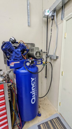
Anyway, I picked up a newer Quincy, a QT-54, from Northern Tool, which should fit nicely in the same place I had the other one.
Additionally, I wanted to make some improvements:
Here are some pictures and brief description of that work.
Pick-up at the freight hub about 45 minutes from here. I did not want them to deliver to my house, because I do not have a good way to lift this off of my gravel driveway into the shop.
This utility trailer had the tailgate permanently attached, which always creates a challenge for forklifts loading things in (unless they were lowered with slings). I finally had enough and cut one of the hinges off so I could remove the tailgate. Later on I would weld it back on, but with the hinges pointing the same direction so that the tailgate can be removed easily (in theory).
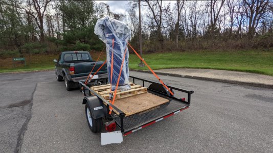
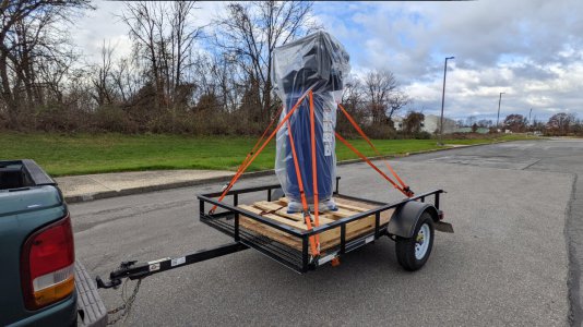
Unloading at home in the garage
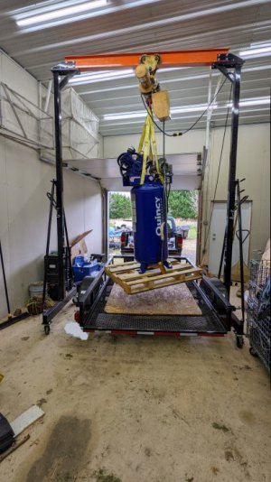
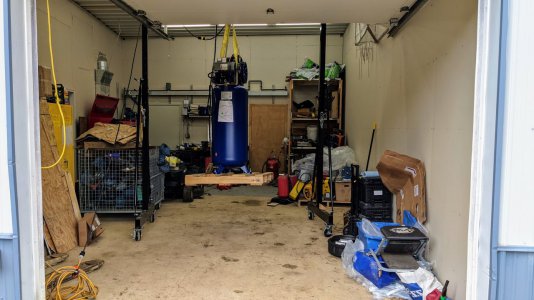
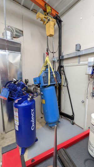
Out with the old, in with the new...
Getting the crane back into this corner is a bit of a chore, especially with how many projects and inventory is currently in the garage. Getting into this corner requires rolling the tool chest away. Rolling the toolchest away requires moving the 750lb welded table out of the way. Moving that table requires making room in the garage, and sweeping the floor so the pallet jack doesn't get hung up on gravel from the driveway ... and so on
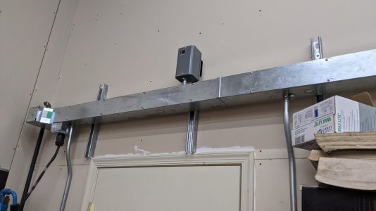
In the picture above you can see the contactor mounted above the doorway.
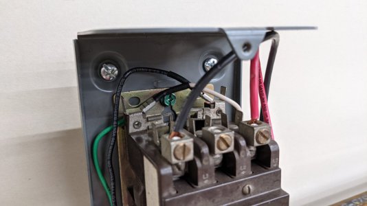
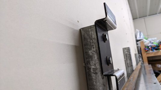
The contactor and enclosure came from a box of misc electrical parts at an auction a year or two ago. To mount this on the existing unistrut I bent up a quick bracket out of a piece of scrap aluminum plate.
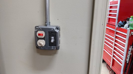
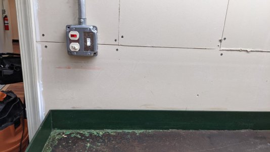
This is fed by the 3-way switches in the garage and the hallway, whose pilot lights indicate whether the contactor has power. I found these switches as a lot of 2 on ebay (new old stock) for a pretty good discount over what they would cost new.
At first I thought it would be nice to install these near the 2 entrances/exits to the building, however that is a lot of pipe and wire for almost no benefit. The two switches shown below are on opposite sides of the same wall (at the shop garage door), where anyone entering/exiting the building can see them from the two outside doors.
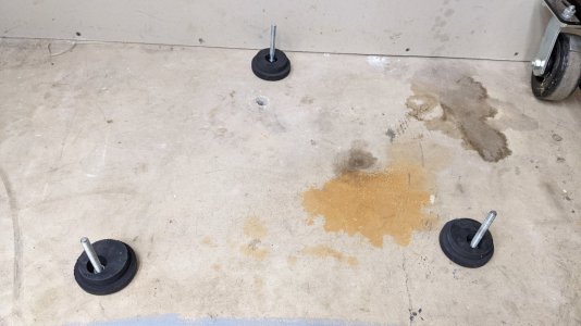
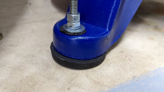
The old compressor was set on 4 hockey pucks which were centered on 3/8 threaded rod going into double-expansion anchors in the floor. The washer above the foot was double-nutted loosely, to avoid clamping to the floor and translating more vibration into the concrete. This worked well, however:
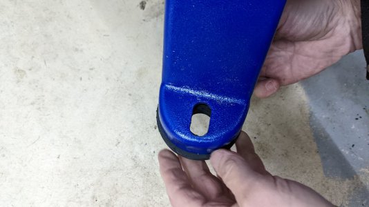
The holes are off-center in the puck, since they are not centered in the radius of the feet. Also I pushed the hole slightly closer to the edge, so that more of the shoulder could protrude out from under the radius of the foot.
Like last time, the nuts above the washer are not clamping the compressor to the floor to avoid resonating excessively in the concrete. However, to keep the washer from potentially rattling around - I took some chips from the puck and used them as a rubber washer under the galvanized washer. These chips were from counterboring the pucks with a Forstener bit -- one of the pucks was made of a rubber that formed really nice spiral chips with a 3/8 hole in the middle, which could be wound around the threaded rod nicely.
At this point I hooked power to the compressor just to confirm no immediate failures/ warranty issues before proceeding, and all was good.
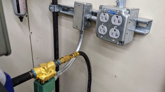
The last piece of work was to plumb in the new solenoid valve (new old stock from eBay, 5 to 250 psi). The compressor is not lined up 100% with how I would like the conduit and future air line to meet the wall/regulator, however this is good enough for now.
In the future I will replace the EMT conduit with flexible metal conduit; and the 3/8 rubber line with a larger diameter flexible line that doesn't have quick-disconnect couplers adding further airflow restriction. At least this 3/8 rubber line is on the high pressure side of the regulator.
Thanks for reading. Not the most interesting shop project but as always maybe it helps others brainstorming upgrades to their compressor setup. Specifically, the contactor + 3-way pilot light switches + solenoid valve for turning the entire system on and off - I am happy with how that install went; and it performs exactly as I would like.
Overall cost for adding those improvements was maybe $50-75 if I had bought everything used or new-old-stock on eBay. The contactor and enclosure came from a larger auction lot, but they can be had cheap on eBay.
There is still more to do:
Anyway, I picked up a newer Quincy, a QT-54, from Northern Tool, which should fit nicely in the same place I had the other one.
Additionally, I wanted to make some improvements:
- Add a contactor to my 30a circuit for the compressor, so that I don't need to use the breaker to turn it on and off
- Install 3-way switches with pilot lights, to control the coil on the contactor. This way as I am exiting the shop via either door, I can see the pilot light and know whether the contactor has power
- Add a solenoid valve immediately outside the tank, controlled by the same 3-way switching; so that the compressor automatically is isolated from the air lines in the shop and leaks don't draw the tank down
Here are some pictures and brief description of that work.
Pick-up at the freight hub about 45 minutes from here. I did not want them to deliver to my house, because I do not have a good way to lift this off of my gravel driveway into the shop.
This utility trailer had the tailgate permanently attached, which always creates a challenge for forklifts loading things in (unless they were lowered with slings). I finally had enough and cut one of the hinges off so I could remove the tailgate. Later on I would weld it back on, but with the hinges pointing the same direction so that the tailgate can be removed easily (in theory).


Unloading at home in the garage


Out with the old, in with the new...
Getting the crane back into this corner is a bit of a chore, especially with how many projects and inventory is currently in the garage. Getting into this corner requires rolling the tool chest away. Rolling the toolchest away requires moving the 750lb welded table out of the way. Moving that table requires making room in the garage, and sweeping the floor so the pallet jack doesn't get hung up on gravel from the driveway ... and so on

In the picture above you can see the contactor mounted above the doorway.

The contactor and enclosure came from a box of misc electrical parts at an auction a year or two ago. To mount this on the existing unistrut I bent up a quick bracket out of a piece of scrap aluminum plate.

This is fed by the 3-way switches in the garage and the hallway, whose pilot lights indicate whether the contactor has power. I found these switches as a lot of 2 on ebay (new old stock) for a pretty good discount over what they would cost new.
At first I thought it would be nice to install these near the 2 entrances/exits to the building, however that is a lot of pipe and wire for almost no benefit. The two switches shown below are on opposite sides of the same wall (at the shop garage door), where anyone entering/exiting the building can see them from the two outside doors.


The old compressor was set on 4 hockey pucks which were centered on 3/8 threaded rod going into double-expansion anchors in the floor. The washer above the foot was double-nutted loosely, to avoid clamping to the floor and translating more vibration into the concrete. This worked well, however:
- The new compressor had 3 feet instead of 4, bummer. On the plus side, the double-expansion anchors are removable so I didn't waste them
- The formed feet of the new compressor are almost the same OD as the pucks. I didn't know whether they might squish into the hollow feet over time
- I did not care for the aesthetic of the hockey pucks


The holes are off-center in the puck, since they are not centered in the radius of the feet. Also I pushed the hole slightly closer to the edge, so that more of the shoulder could protrude out from under the radius of the foot.
Like last time, the nuts above the washer are not clamping the compressor to the floor to avoid resonating excessively in the concrete. However, to keep the washer from potentially rattling around - I took some chips from the puck and used them as a rubber washer under the galvanized washer. These chips were from counterboring the pucks with a Forstener bit -- one of the pucks was made of a rubber that formed really nice spiral chips with a 3/8 hole in the middle, which could be wound around the threaded rod nicely.

At this point I hooked power to the compressor just to confirm no immediate failures/ warranty issues before proceeding, and all was good.
The last piece of work was to plumb in the new solenoid valve (new old stock from eBay, 5 to 250 psi). The compressor is not lined up 100% with how I would like the conduit and future air line to meet the wall/regulator, however this is good enough for now.
In the future I will replace the EMT conduit with flexible metal conduit; and the 3/8 rubber line with a larger diameter flexible line that doesn't have quick-disconnect couplers adding further airflow restriction. At least this 3/8 rubber line is on the high pressure side of the regulator.

Thanks for reading. Not the most interesting shop project but as always maybe it helps others brainstorming upgrades to their compressor setup. Specifically, the contactor + 3-way pilot light switches + solenoid valve for turning the entire system on and off - I am happy with how that install went; and it performs exactly as I would like.
Overall cost for adding those improvements was maybe $50-75 if I had bought everything used or new-old-stock on eBay. The contactor and enclosure came from a larger auction lot, but they can be had cheap on eBay.

There is still more to do:
- The 3/8 rubber line from the valve to the regulator is for certain a bottleneck in the system. At some point I will plumb this in more directly and without quick-connects. Either rubber or braided stainless flexible line (to avoid carrying vibration into the entire pipe system)
- Similarly, I will eventually like to replace the piece of EMT conduit from the valve with a short piece of FMC, once I come across a scrap of that.
- There is quite a bit more pipe I want to run in the shop, time permitting
- Not an improvement but an observation/comment to share in case anyone was wondering the same -- this corner in theory might not provide ideal airflow for the compressor to cool itself. However, my use cases are all low duty cycle; and there is still reasonable airflow clearance around it -- especially if the door to the hallway is not propped open.
- Selling the parts or complete old compressor, as described above
- I have since purchased 2 more of these contactors and enclosures used on eBay, so that I can have a 120v switch control a few 30a breakers for garage heaters mounted on the wall. A single switch for turning those on and off seems better than going to the breaker panel or having to go on a step ladder to turn the units on.
Last edited:

