- Joined
- Nov 5, 2016
- Messages
- 1,419
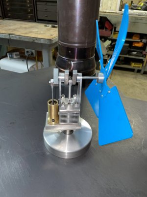
Test running my latest project, a Moriya stirling engine fan for my woodstove. Besides being able to use my machine shop tools I was even able to get my Prusa MK3S+ 3D printer into the act making the fan blade ( PTEG blue, my grandson’s current favorite color; he's 5 ). RPM varies with temperature, but at around 500 degrees it’s currently running at ~400 RPM. Should speed up when it gets broken in. Just a nice, gentle breeze to help move the heat around a little in my basement hobby shop.
The design is by Dr. James R. Senft and the drawings are available for free on the internet. I was happy with the fact that I had all the raw materials on hand except for the #4-40 socket head cap screws. Material costs have skyrocketed lately, especially brass and aluminum! And I like being able to make stuff with materials I’ve got on hand...
Mostly done now. I'm still thinking about the fan guard... I at least need something to pick the fan up quickly when it's hot incase something comes loose while running.
Cutting the cooling fins in the cold end.
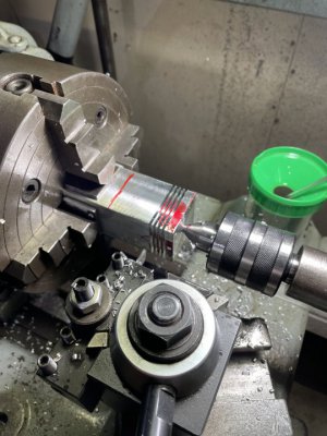
I trepanned the lightening recess on my lathe. Trepanning is always a little nerve racking especially when using a long, narrow tool.... make sure the tool isn't touching where it's not suppose to touch! I used Dykem to check for any undesirable contact.
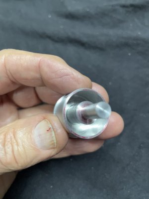
Brass sleeve bearing in the power connecting rod.
I made the displacer piston body out of a solid piece of stainless steel. Cylinder and end all one piece. Made the Hot end out of a solid piece of steel square stock. Flange, cylinder and end all one piece. No need for silver soldering...
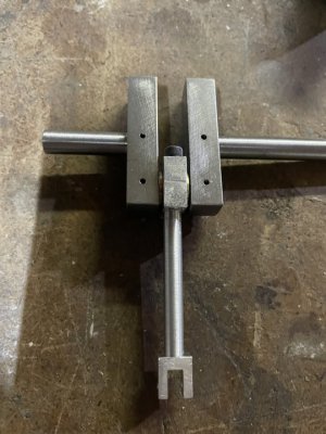
The crank. Close fit, pinned and Loctite.
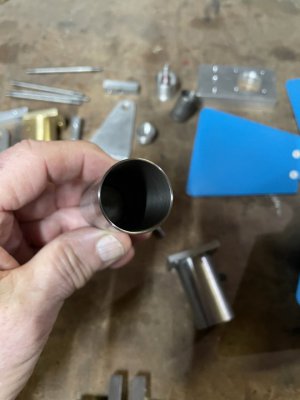
The displacer tube. Around 0.020" wall if I remember correctly. Not sure what grade stainless it is. Not free machining that's for sure! Stainless has better thermal characteristics than making it out of aluminum, although a little heavier. It has such a thin wall weight doesn't seem to be an issue.
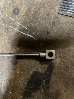
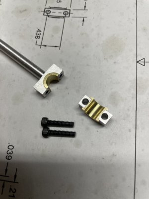
Made a split brass bearing for the displacer connecting rod. (2) #4-40 screws hold the cap on.
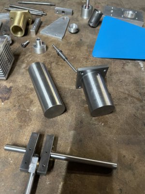
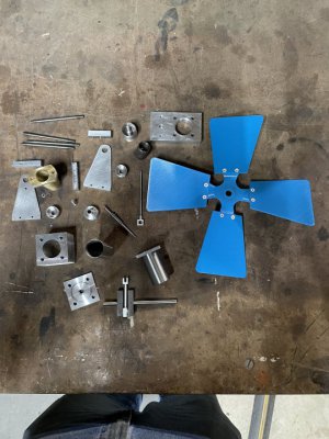
All the parts (except for the gaskets and base). The gland/displacer shaft and the power cylinder/power piston where both lapped in for a nice, tight, friction free fit.
Ted
The design is by Dr. James R. Senft and the drawings are available for free on the internet. I was happy with the fact that I had all the raw materials on hand except for the #4-40 socket head cap screws. Material costs have skyrocketed lately, especially brass and aluminum! And I like being able to make stuff with materials I’ve got on hand...
Mostly done now. I'm still thinking about the fan guard... I at least need something to pick the fan up quickly when it's hot incase something comes loose while running.

Cutting the cooling fins in the cold end.

I trepanned the lightening recess on my lathe. Trepanning is always a little nerve racking especially when using a long, narrow tool.... make sure the tool isn't touching where it's not suppose to touch! I used Dykem to check for any undesirable contact.

Brass sleeve bearing in the power connecting rod.

I made the displacer piston body out of a solid piece of stainless steel. Cylinder and end all one piece. Made the Hot end out of a solid piece of steel square stock. Flange, cylinder and end all one piece. No need for silver soldering...

The crank. Close fit, pinned and Loctite.

The displacer tube. Around 0.020" wall if I remember correctly. Not sure what grade stainless it is. Not free machining that's for sure!

Made a split brass bearing for the displacer connecting rod. (2) #4-40 screws hold the cap on.

All the parts (except for the gaskets and base). The gland/displacer shaft and the power cylinder/power piston where both lapped in for a nice, tight, friction free fit.

Ted


