MT5 to 5C Taper Adapter

Ray C

Registered
Registered
Joined
Nov 16, 2012
Messages
5,596
OK, I needed to make myself another MT5 to 5C taper adapter and another member needed one as well so here it is. Very easy to make but it's best if you draw it out first.

Here's a cross-sectional view as well as the dimensions for a spindle that has 1.5" diameter bore at the mouth. These dimensions won't work in a PM1236 machine. The adapters are custom sized depending on your spindle bore diameter. The MT5 angle is the same but the overall dimensions are different.

View attachment MT5_5C_Adapter-dims.pdf
View attachment MT5_5C_Adapter-sv.pdf

The one I made is slightly different than the drawn plans because the piece of stock I had on-hand was slightly less in diameter than what I thought. Also, I made the collar a little bit wider. These are inconsequential modifications. It's made of 1045 and I'll heat treat it this weekend. Here's a play-by-play:

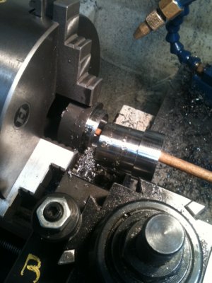
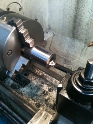
First, the outer OD was turned to maximum size. This one is just shy of the 1.8" I planned to make it since the starting shaft was 1.75". I just made one pass on the outside to get the scale off. Not show here but, I bored a 1" hole down the center then did a precision bore to 1.260". The maximum main shaft dimension of a 5C collet is 1.25" so I gave a little clearance.
T1.JPG

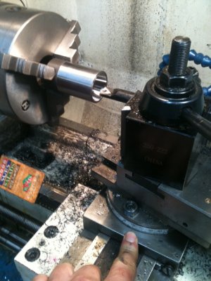
Next, the compound was set for 10[SUP]o[/SUP] (corresponding to the 5C spec) and the inner taper was opened up to the spec show in the diagram (which I believe is 1.475").
T2.JPG

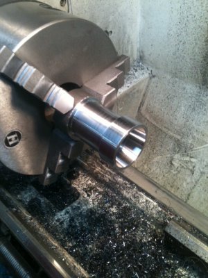
After that, the compound was set to 1.5073[SUP]o[/SUP]. The angel was carefully set by using travel indicators and measuring rise over run. The angle was then cut on the outside of the adapter. I measured-off from the front of the adapter, where the taper should end. In about 3-4 passes, the taper was cut from right to left.
T3.JPG

Basically done... Just part it off.

T4.JPG

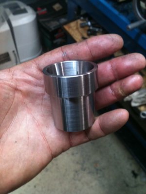
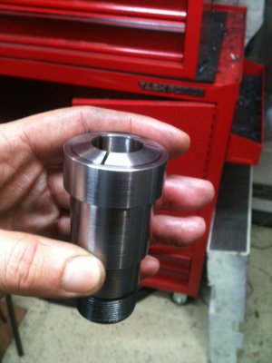
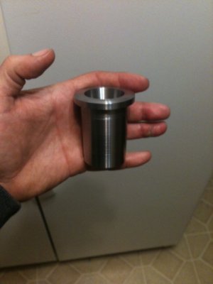
And here's what it looks like...

T5.JPGT6.JPG


I'll heat treat it this weekend.

Ray

T1.JPG T2.JPG T3.JPG T4.JPG T5.JPG T6.JPG
 

Attachments

  • MT5_5C_Adapter.pdf
    63.2 KB · Views: 71
Do realize that once you make one of these, all you need to do is thread an appropriately fitting tube to go through your spindle and make a collar nut -and bingo... You got your own 5C collet closer for about 15 bucks -instead of paying a couple hundred for a store-bought one. I made one for myself but, I have this bad habit of using the metal for other projects and I can't find the other adapters or spindle tube. I know I made one a while back...

I'll draw-up and post the dimensions for a PM1236 lathe sometime soon.


Ray
 
OK, I needed to make myself another MT5 to 5C taper adapter and another member needed one as well so here it is. Very easy to make but it's best if you draw it out first.

Here's a cross-sectional view as well as the dimensions for a spindle that has 1.5" diameter bore at the mouth. These dimensions won't work in a PM1236 machine. The adapters are custom sized depending on your spindle bore diameter. The MT5 angle is the same but the overall dimensions are different.

View attachment 64019
View attachment 64012

The one I made is slightly different than the drawn plans because the piece of stock I had on-hand was slightly less in diameter than what I thought. Also, I made the collar a little bit wider. These are inconsequential modifications. It's made of 1045 and I'll heat treat it this weekend. Here's a play-by-play:

First, the outer OD was turned to maximum size. This one is just shy of the 1.8" I planned to make it since the starting shaft was 1.75". I just made one pass on the outside to get the scale off. Not show here but, I bored a 1" hole down the center then did a precision bore to 1.260". The maximum main shaft dimension of a 5C collet is 1.25" so I gave a little clearance.

View attachment 64013

Next, the compound was set for 10[SUP]o[/SUP] (corresponding to the 5C spec) and the inner taper was opened up to the spec show in the diagram (which I believe is 1.475").

View attachment 64014

After that, the compound was set to 1.5073[SUP]o[/SUP]. The angel was carefully set by using travel indicators and measuring rise over run. The angle was then cut on the outside of the adapter. I measured-off from the front of the adapter, where the taper should end. In about 3-4 passes, the taper was cut from right to left.

View attachment 64015

Basically done... Just part it off.

View attachment 64016

And here's what it looks like...

View attachment 64017View attachment 64018


I'll heat treat it this weekend.

Ray

LOVE this. I like to make anything that allows me to use 5C as much as possible!
Thanks Ray!

Bernie
 
Thanks. Glad you like it.

Do realize that the dimensions provided may not work on your lathe because there is no standard about the hole diameter in a spindle. The only stipulation is the angle must match the MT5 spec (assuming of course, the spindle is MT5). Since the bore diameter at the mouth of the opening could be different among lathes, you'll need to make an adapter for your particular spindle.

Anyhow... the drawings are provided to give you a feel for what's going on.

So, Bernie, are you going to make one?

LOL: I found the pipe that I threaded from last time. It was cut in half and I remember now, I used the other half on a temporary welding jig. I also found the end nut. That was intact...

Ray

PS: The dimensions of the adapter for the PM1236 will allow you to use a full 1-1/8 collet and still have the ability to put a rod all the way through it. Believe it or not, it took a few minutes of measuring and CAD work to get the dimensions right.


LOVE this. I like to make anything that allows me to use 5C as much as possible!
Thanks Ray!

Bernie
 
Ray,
do you plan on doing any "touch up" after heat treating, like light pass with tool post grinder to 5C taper, or this should be finished product before/after heat treating? Any expectations of dimensional changes?

Thanks for all of your posts, very much appreciated !!!!

Dan
 
Hi Dan...

Thanks for the kind words.

Possibly, yes. Heat treating can slightly warp things -especially if there are vast changes in part thickness because thicker areas cool off slower than thin areas during the quench. Also, depending on the material, there could be very slight shrinkage or expansion -but it is barely measurable for small to medium sized parts. Last, parts that are overheated by as little as 100F degrees beyond the austentizing temperature and if heat soaked too long could sag (a common mistake).

Anyhow, for heat treated parts, I always leave some trued-up non non-critical surfaces so they can be mounted in a chuck etc (in this case, the collars). When I plan to grind after heat treating, I oversize parts about (depending on size of the overall part) 3 thou. For these parts, I don't expect significant dimensional changes and highly doubt anything will need to be done afterward. It's a very "symmetric" part. I'll just sandblast them. Generally, in order to reveal the true hardness, parts should be surface ground etc because the outer 1-2 thou skin layer is damaged by oxidation. For things like this, its nothing to lose sleep over.

BTW: I love the look of ground heat treated material. The results are stunning.

Ray

EDIT: If you look at the cross-sectional diagrams that were posted, I intentionally designed things so there would be uniform thickness as it transitioned from shaft to collar. This was done for strength as well has head-off any distortion problems.


Ray,
do you plan on doing any "touch up" after heat treating, like light pass with tool post grinder to 5C taper, or this should be finished product before/after heat treating? Any expectations of dimensional changes?

Thanks for all of your posts, very much appreciated !!!!

Dan
 
Back in March of 2010 I purchased one of these adapters from Grizzly for $30. I just checked to see if they still stocked them and they do, for $98 !!! Glad I shopped early

Joe
 
Dinner is cooking in the oven. Tonight's menu: 1045 cooked to perfection at 1550F. Temperature brought-up very slowly this time (to allow all the seasoning to flavor:), 200 degrees at a time. This goes a long way to prevent warping. 3 gallons of brine water waiting. The circulating pump will be turned on just before the big chill. Tempering will be done immediately after they get to 200F. Tempering at 650F for 1 hour followed by an air cool. I measured all dimensions very closely beforehand.


Ray
 
Back
Top