- Joined
- Sep 28, 2013
- Messages
- 4,319
Next project on the list, that's been waiting in the wings since the summer.
I work on a nematode called C. elegans, which is very cool in many ways, but one of the best (and Nobel prize winning) tricks it has is that you can make transgenic worms which glow green. Not just for fun, but also to see where genes are expressed or how proteins are being regulated. The thing that makes them glow green is a protein called Green Fluorescent Protein, GFP for short, which was discovered in a jelly fish A. victoria (https://en.wikipedia.org/wiki/Green_fluorescent_protein). Since then a bunch of other fluorophores were discovered, Red, Yellow, Cyan etc from jelly fish and coral (I think), so you can have multiple different colours in the same animal. All of these fluorophores share the same attributes - they're all excited by a specific wavelength of light and re-emit that light at a different, higher wavelength.
GFP needs between 395 (UV) and 475nm (blue) for excitation and emits at 509nm (lower end of green spectrum). So to work with GFP, you need a UV or blue light source and a filter that blocks out all light below ~500nm. Light sources used to be white mercury lamps or metal halide bulbs (what I used in my last job, what a PITA), with filters to let only blue light through. With LEDs, which can emit at very narrow frequencies, alot of manufacturers are now using different colour LEDs as the light source (typically individual LEDs in a carousel) which is more efficient because a) LEDs are more efficient than filament or HID bulbs and b) you only generate the wavelength you want instead of stripping it out of a whole bunch you don't want.
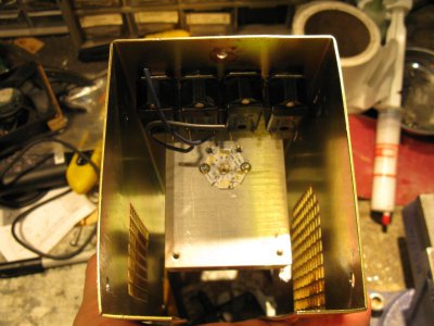
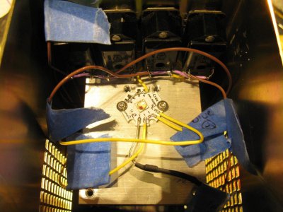
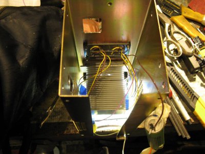
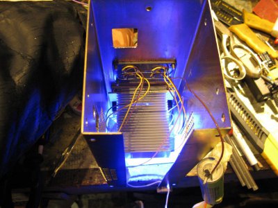
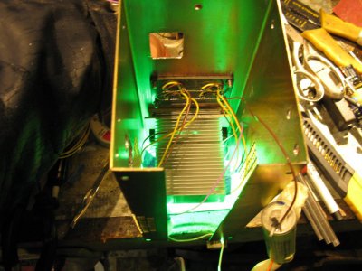
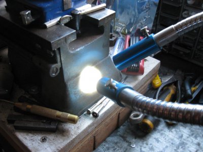
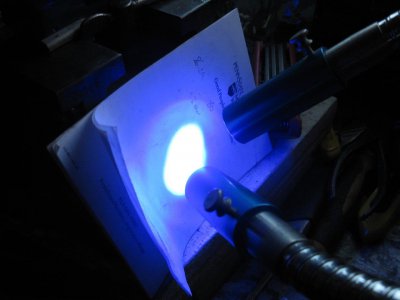
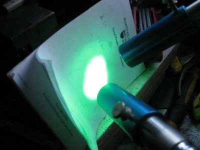
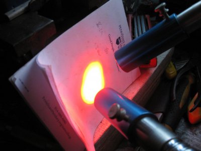
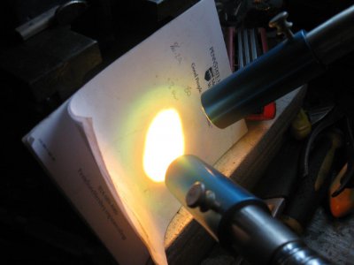
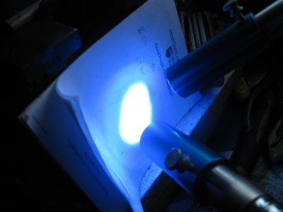
Anyway, long blurb short, where I work now (temp professor at Whitman College) has an LED blue light source on their inverted scope, which is pretty cool, but you can only look at objects on glass slides with it. I do a lot of work (genetic crosses etc) on agar plates, which I can't easily do without a blue light source on a dissecting scope. So I used some of my research funds from last year and the summer to buy an adapter for the dissecting scopes we have at work and a green band pass filter, plus a multicolour Cree LED (white, blue, green and red on one LED!), some switches and with a whole bunch of bits'n'pieces in my garage, I'll be making a multicolour LED light source!
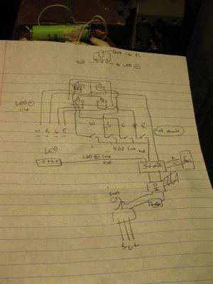
It's going to be really basic, with 4 individually switched channels, each with 2 x 350mA AMC7135 current regulators for 700mA total. I hope that is both enough and not too much. If it's not enough, I'll add another chip, if it's too much I'll see if I can add an extra channel for each colour with only 1 chip. We'll see.
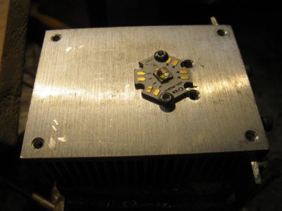
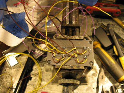
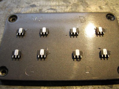
First task, make a plate with the chips JB welded to it. They're really fiddly to handle, so this will hold them in place, plus the heatsinking won't hurt. Used a random piece of scrap and tapped the existing holes 6-32.
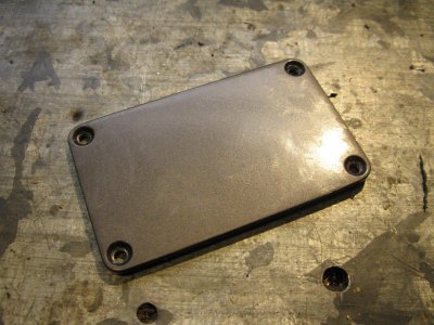
Each chip has a ground leg (to negative leg of power source, be it battery or 5V DC) which is the large center one, a negative drain leg (to negative side of LED) and a Vdd leg which turns the chip on and allows current to flow. I can never remember which is which so I'll dig out a diagram before wiring them up.
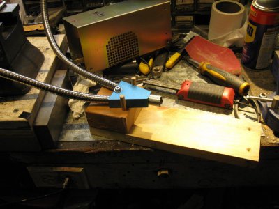
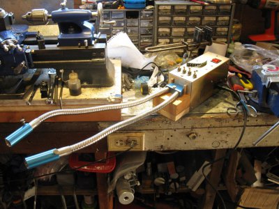
made a little adapter collar for the fiber optic arm things that will carry the light to the sample. Should have been more careful with my cuts, but it polished up well enough with a series of finer grit sandpapers wrapped around a pencil and then a polish with Mothers.
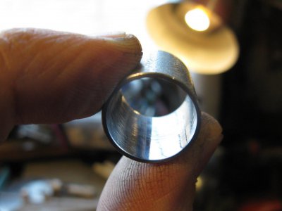
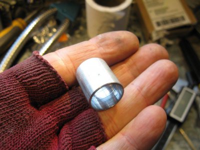
lightly JB Welded in place. The idea here is that it will help capture stray light that comes out of the sides of the LED and hopefully direct it down the fiber optic.
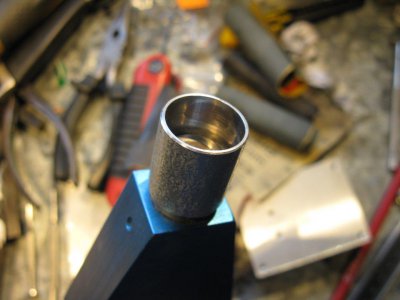
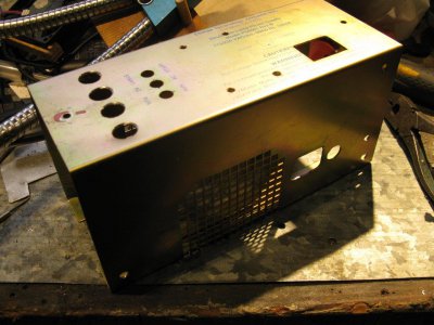
those have to set overnight plus it's Friday Family Film night, so that's probably it until tomorrow. Next is to mount the LED on the heatsink (out of focus on the right in the above picture) and the optic on some kind of base, so I can start working on the case.
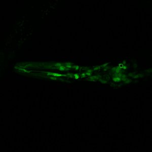
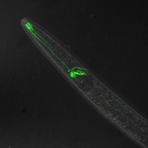
here's some pics of worms I have made
some head muscle, neurons and the intestine (top right)
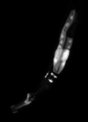
a whole bunch of neurons in the head of a worm
dye filling some neurons
I work on a nematode called C. elegans, which is very cool in many ways, but one of the best (and Nobel prize winning) tricks it has is that you can make transgenic worms which glow green. Not just for fun, but also to see where genes are expressed or how proteins are being regulated. The thing that makes them glow green is a protein called Green Fluorescent Protein, GFP for short, which was discovered in a jelly fish A. victoria (https://en.wikipedia.org/wiki/Green_fluorescent_protein). Since then a bunch of other fluorophores were discovered, Red, Yellow, Cyan etc from jelly fish and coral (I think), so you can have multiple different colours in the same animal. All of these fluorophores share the same attributes - they're all excited by a specific wavelength of light and re-emit that light at a different, higher wavelength.
GFP needs between 395 (UV) and 475nm (blue) for excitation and emits at 509nm (lower end of green spectrum). So to work with GFP, you need a UV or blue light source and a filter that blocks out all light below ~500nm. Light sources used to be white mercury lamps or metal halide bulbs (what I used in my last job, what a PITA), with filters to let only blue light through. With LEDs, which can emit at very narrow frequencies, alot of manufacturers are now using different colour LEDs as the light source (typically individual LEDs in a carousel) which is more efficient because a) LEDs are more efficient than filament or HID bulbs and b) you only generate the wavelength you want instead of stripping it out of a whole bunch you don't want.
Anyway, long blurb short, where I work now (temp professor at Whitman College) has an LED blue light source on their inverted scope, which is pretty cool, but you can only look at objects on glass slides with it. I do a lot of work (genetic crosses etc) on agar plates, which I can't easily do without a blue light source on a dissecting scope. So I used some of my research funds from last year and the summer to buy an adapter for the dissecting scopes we have at work and a green band pass filter, plus a multicolour Cree LED (white, blue, green and red on one LED!), some switches and with a whole bunch of bits'n'pieces in my garage, I'll be making a multicolour LED light source!
It's going to be really basic, with 4 individually switched channels, each with 2 x 350mA AMC7135 current regulators for 700mA total. I hope that is both enough and not too much. If it's not enough, I'll add another chip, if it's too much I'll see if I can add an extra channel for each colour with only 1 chip. We'll see.
First task, make a plate with the chips JB welded to it. They're really fiddly to handle, so this will hold them in place, plus the heatsinking won't hurt. Used a random piece of scrap and tapped the existing holes 6-32.

Each chip has a ground leg (to negative leg of power source, be it battery or 5V DC) which is the large center one, a negative drain leg (to negative side of LED) and a Vdd leg which turns the chip on and allows current to flow. I can never remember which is which so I'll dig out a diagram before wiring them up.

made a little adapter collar for the fiber optic arm things that will carry the light to the sample. Should have been more careful with my cuts, but it polished up well enough with a series of finer grit sandpapers wrapped around a pencil and then a polish with Mothers.


lightly JB Welded in place. The idea here is that it will help capture stray light that comes out of the sides of the LED and hopefully direct it down the fiber optic.

those have to set overnight plus it's Friday Family Film night, so that's probably it until tomorrow. Next is to mount the LED on the heatsink (out of focus on the right in the above picture) and the optic on some kind of base, so I can start working on the case.
here's some pics of worms I have made
some head muscle, neurons and the intestine (top right)

a whole bunch of neurons in the head of a worm

dye filling some neurons


