- Joined
- Oct 21, 2021
- Messages
- 63
Hey Everyone,
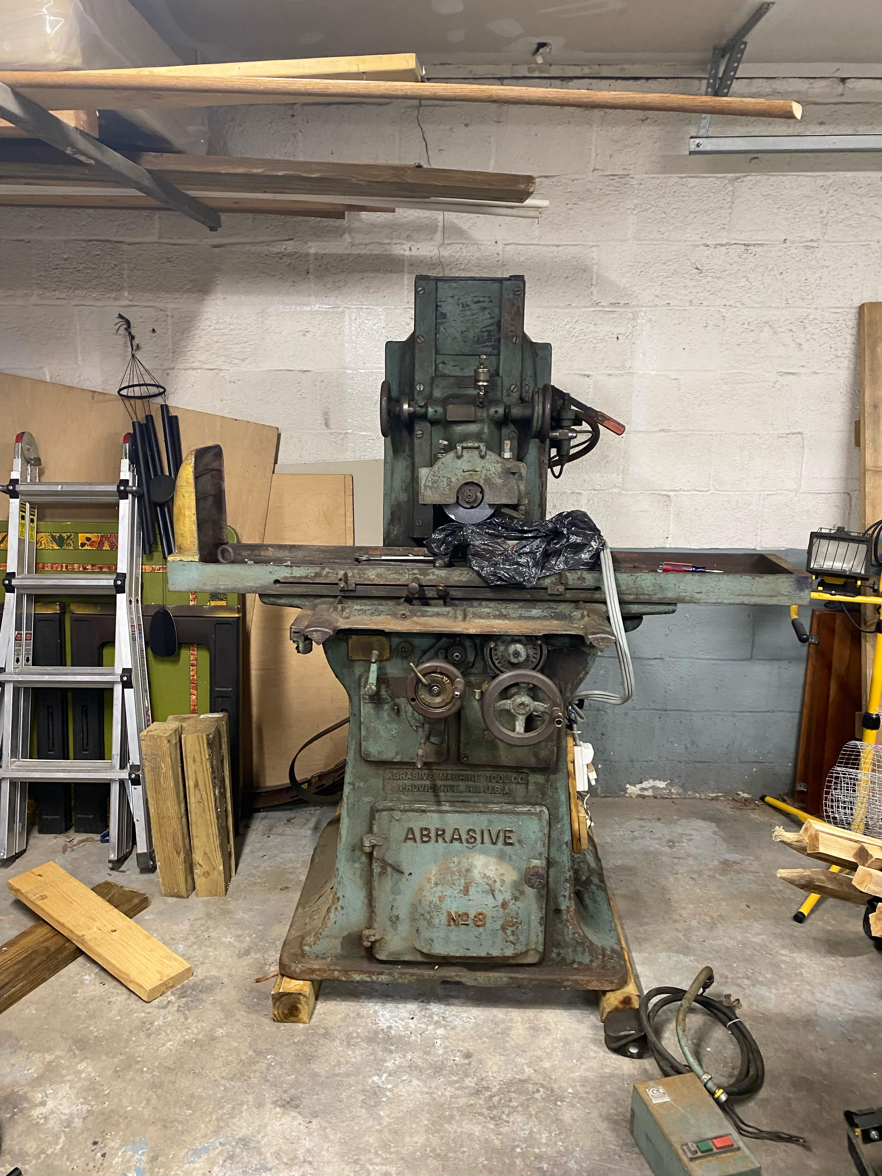
I brought this machine up in the electrical section, as that was my first priority to fix, but with my mcmaster order submitted I decided to poke around and just talk more generally about it here. I picked up this:
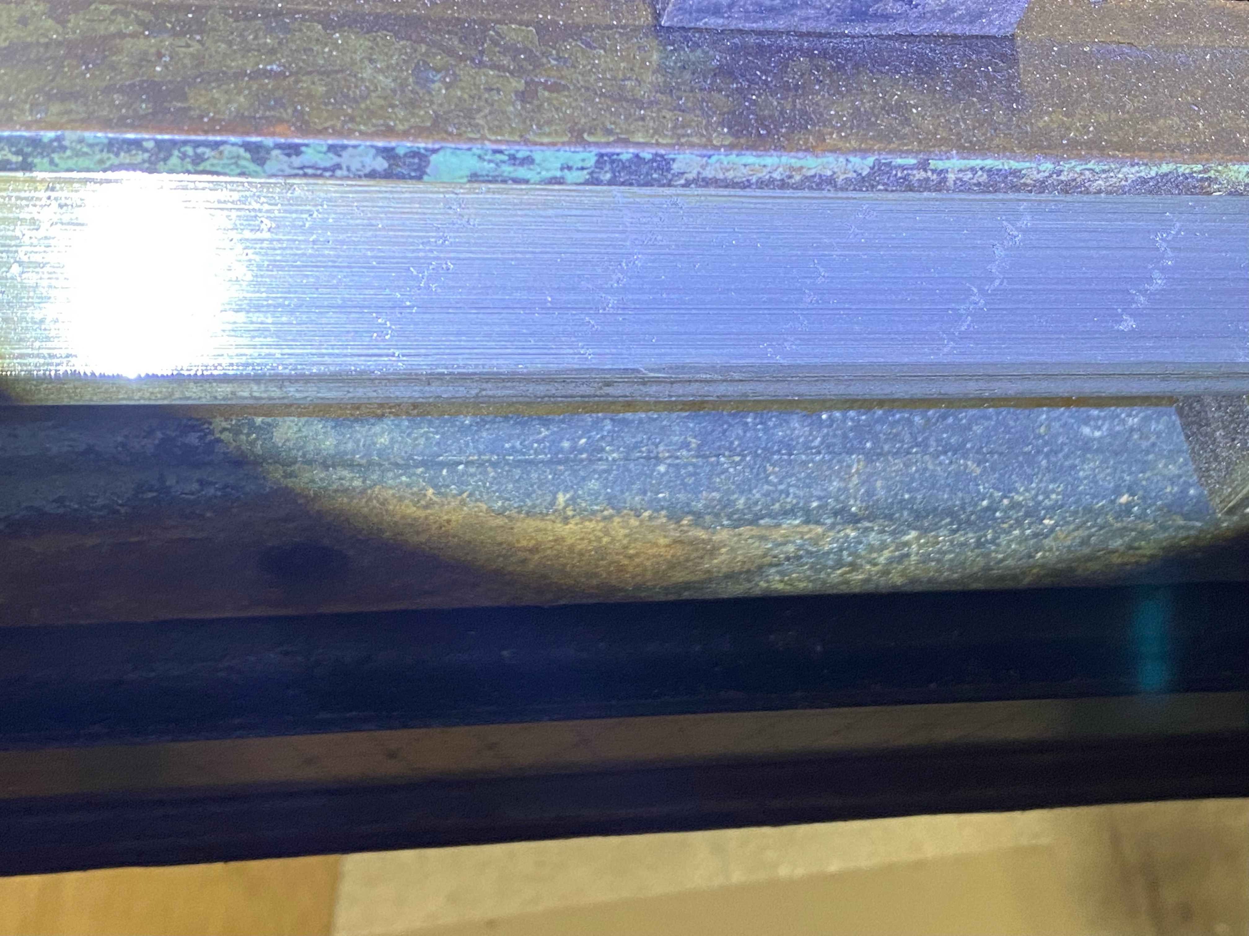
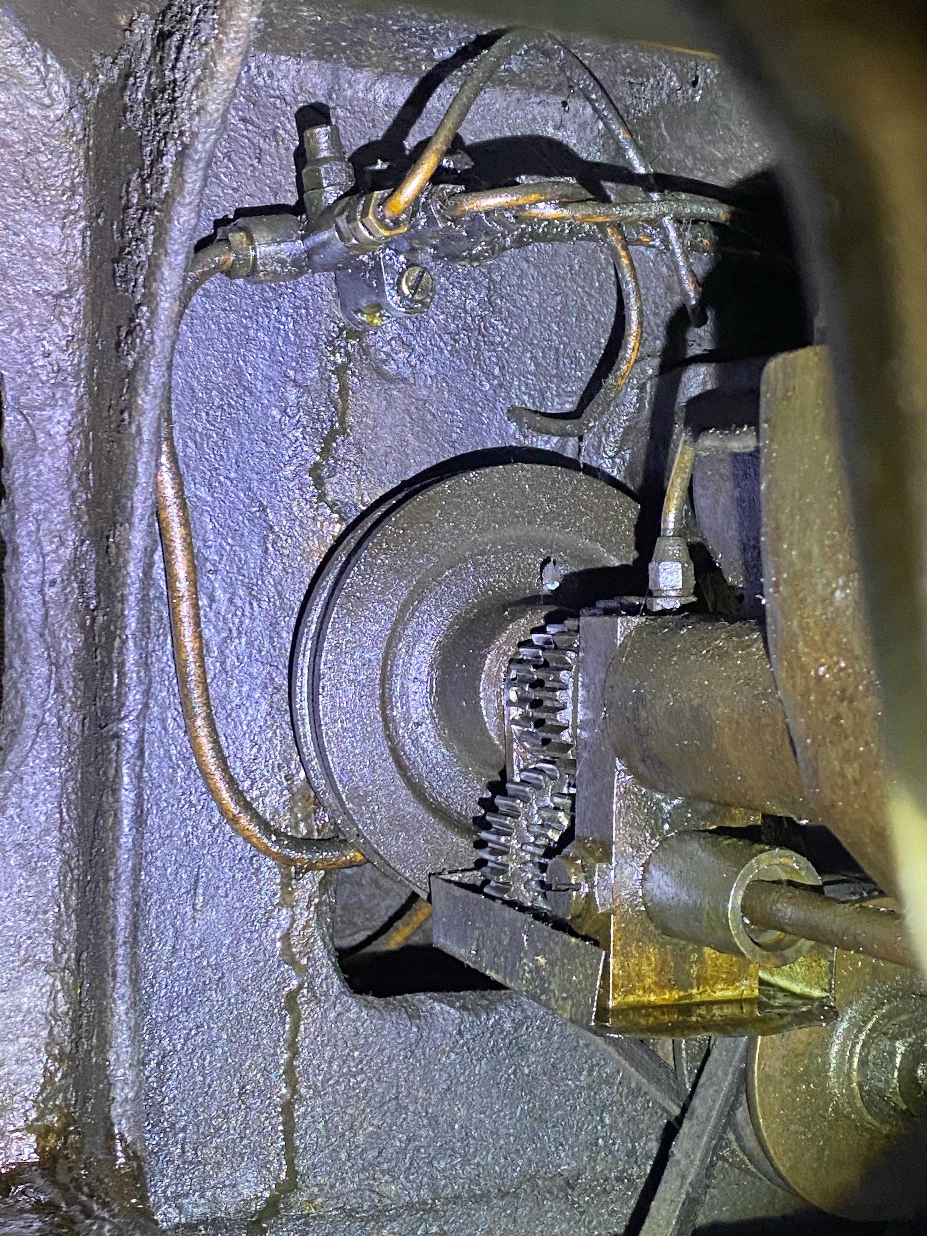
And have been slowly deciphering what's up with it. I got the electrical figured out in this thread here. Today I started evaluating what I saw vs what I have seen in the little documentation I have. The oil system looks ok everywhere that its visible, but it still leaves a huge puddle on the floor almost immediately after pumping it, so I went hunting for the cause. First thing I noticed was the idler is alllll the way to the floor, so I'm gonna have to fix the belt, but I also noticed a hose attached to it.
Any ideas what that hose might be for? Is it just to lubricate the thing? Is this a pump of some sort? The only info I have found in the diagrams is this picture:
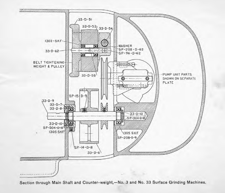
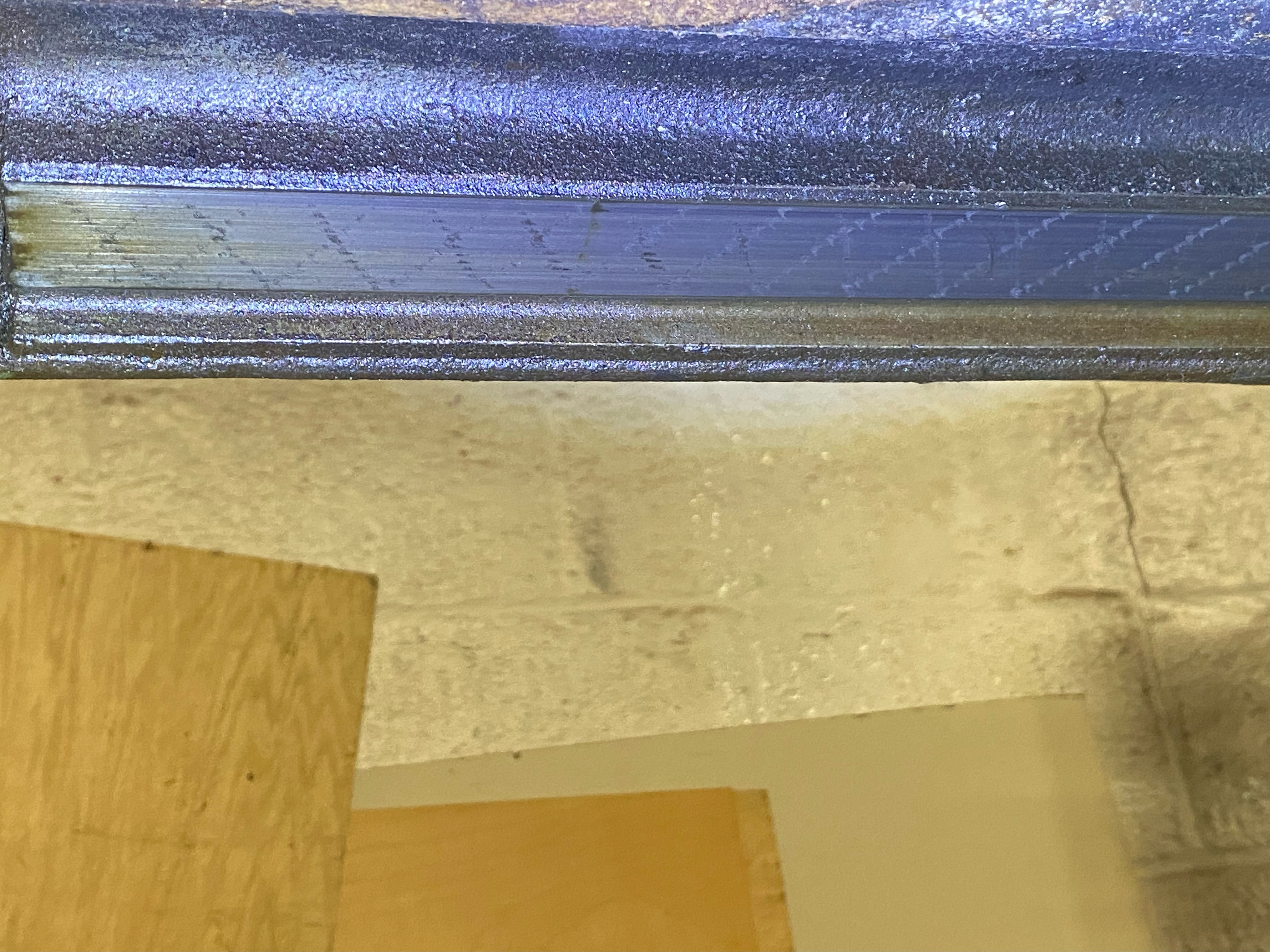
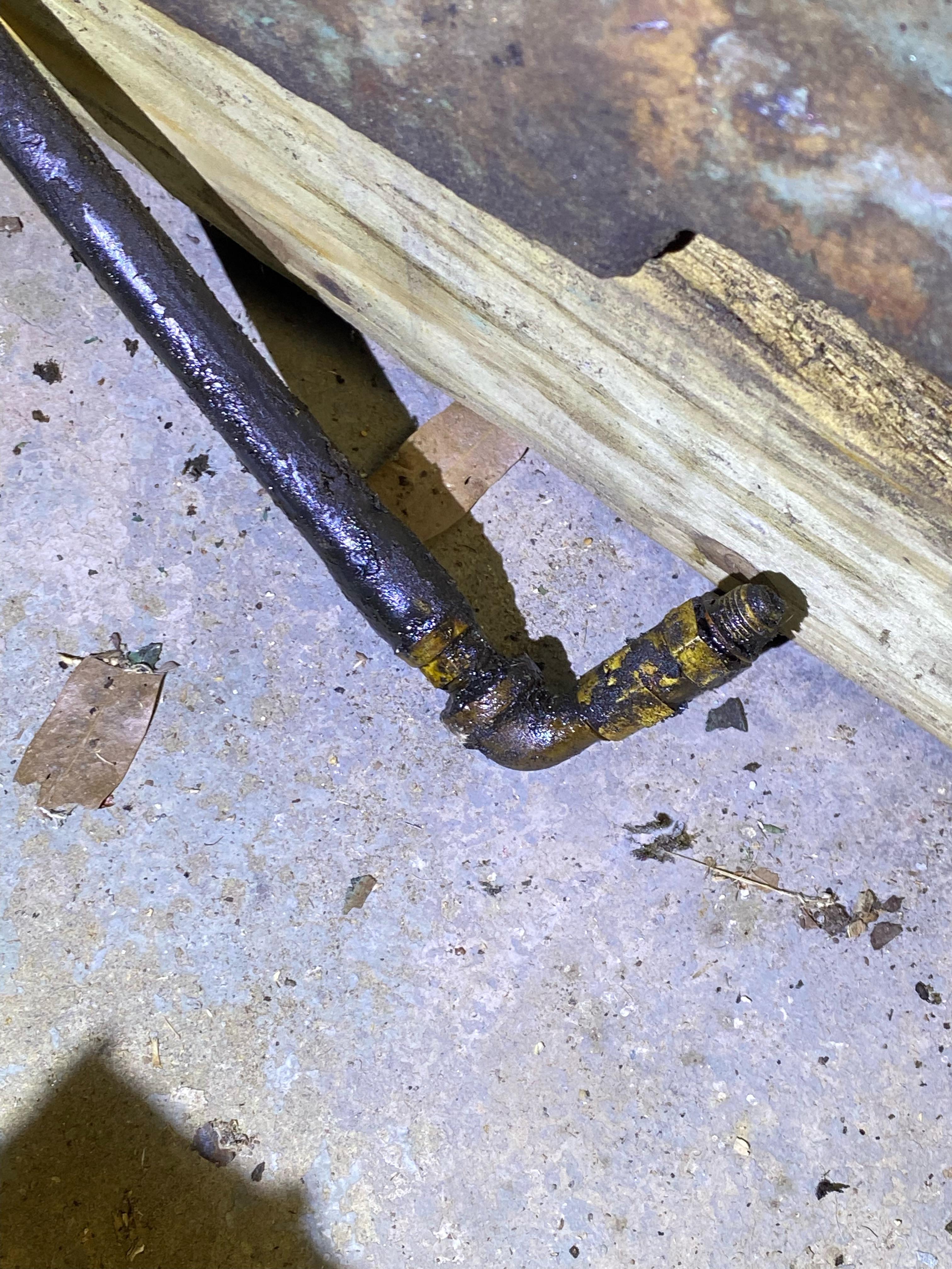
Unfortunately I don't have any of the parts mapped to those numbers, just the illustrations, so I'm flying blind as to it's purpose. While a fair number of parts are the same between the No. 3 and the No. 3B, the belt system was reworked between them, so that's one area I wasn't able to pull knowledge from. Anyway, I traced that hose, and found it wasn't hooked into anything, just an unscrewed connector:
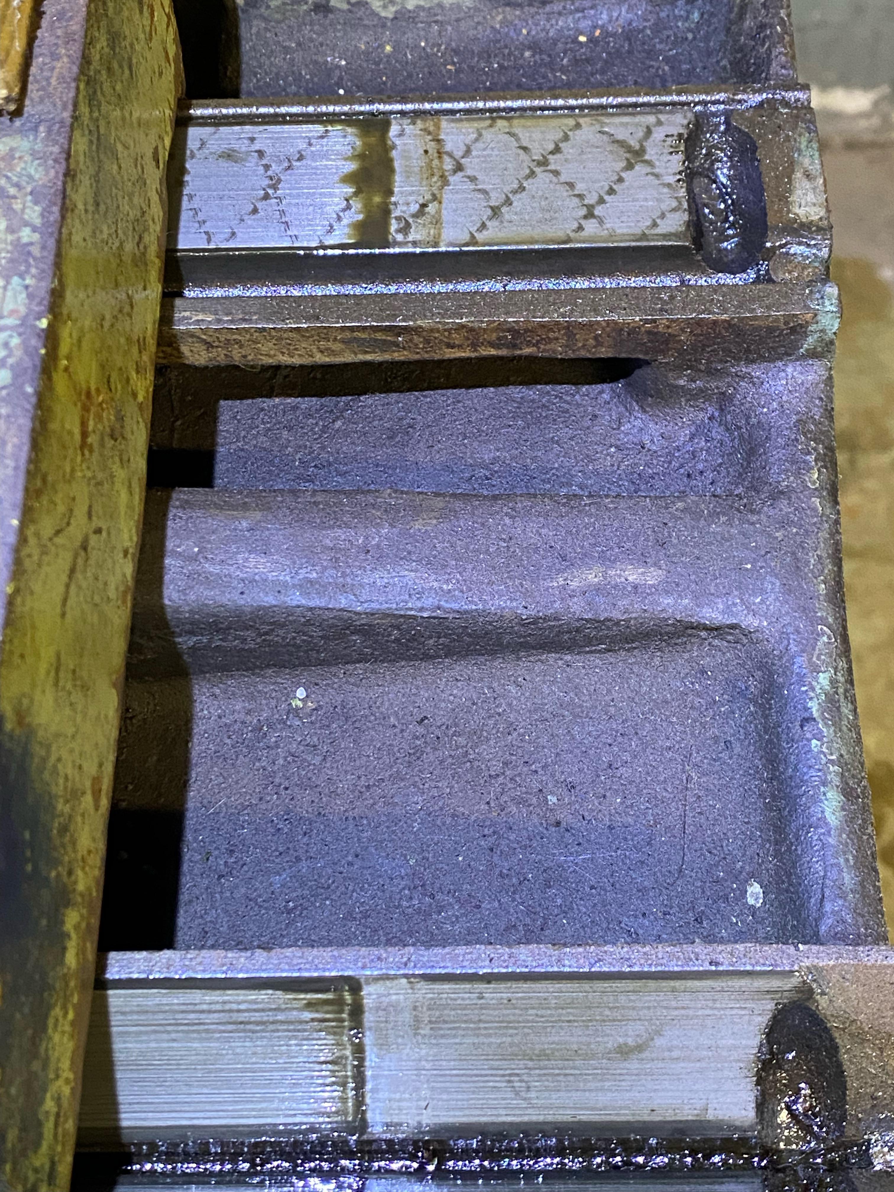
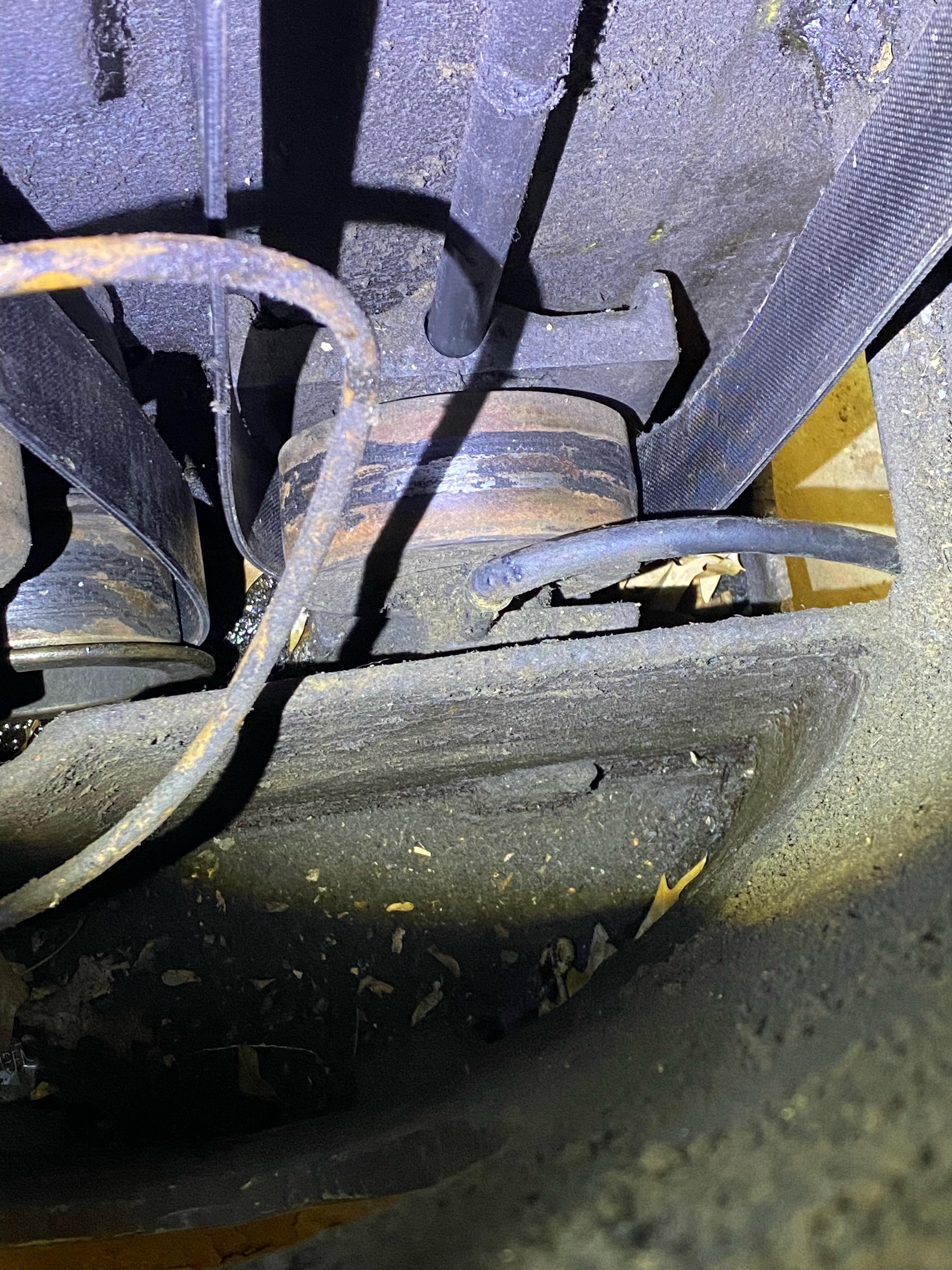
So, following the rest of the oil lines, I wiggled my way around the machine, until I got under the table, and was greeted by a ton of oil, and a junction block in the way back.
Is that a connection to nothing back there? I was able to get my phone about halfway in there and snap a bit closer of a shot:
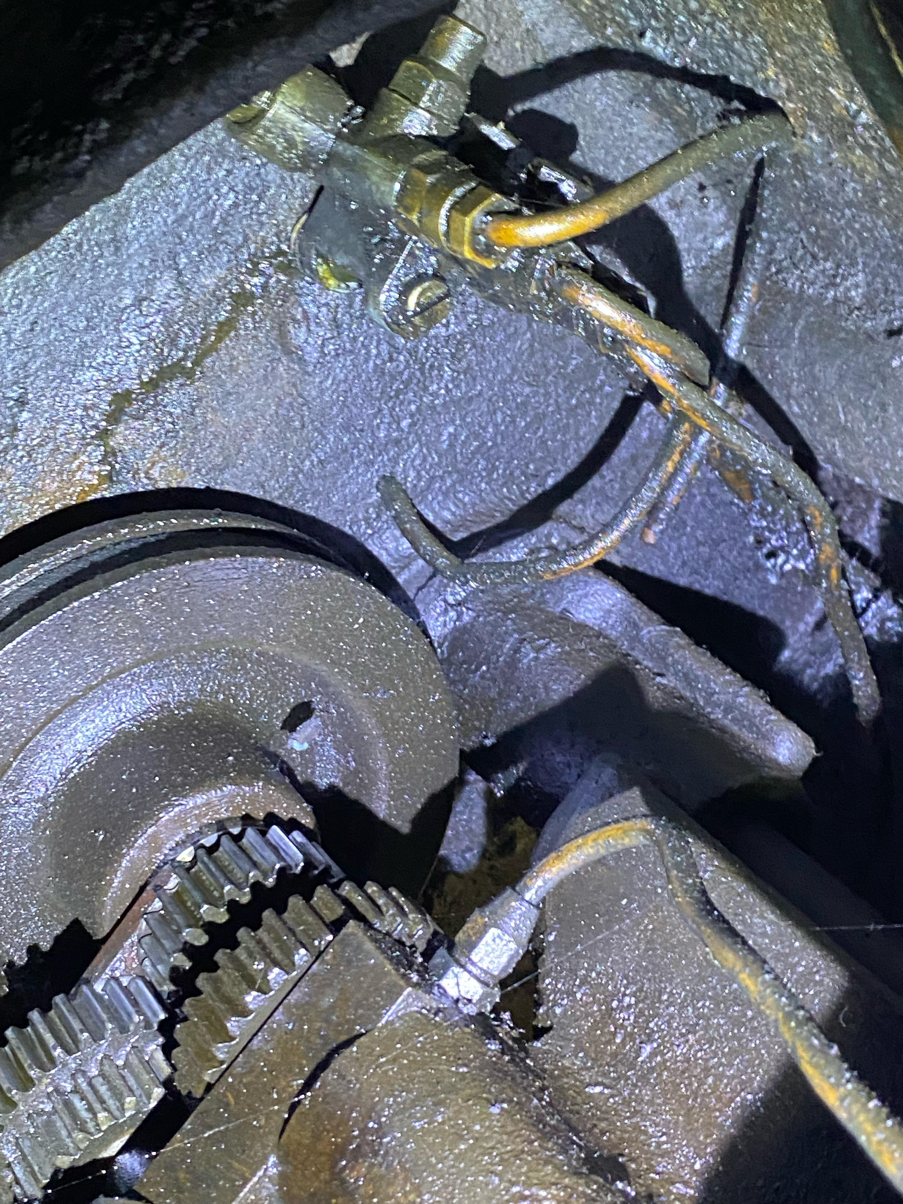
It certainly looks like something belongs there, but I have no idea how to reach it. From where I had access to take this picture its about 3 ft into the casting through a 6x6 hole. Below and to the right there is all the drive equipment for the table feed, and I'm not sure of myself enough to take that out on my own just yet, so I'm not sure what to do just yet at this juncture. My first thought was to just lube up that pulley and cap it with some sort fitting, but now I'm second guessing that it should be hooked up to something. Likewise I'd like to at least plug that hole to make sure everything else is getting the oil it needs, but I guess for now it'll just stay leaking.
The grinder seems in pretty decent shape, to my untrained eye at least. I haven't had a chance to run it yet as I'm waiting on some electrical fixes, but with the tensioner bottomed out the belt is still incredibly loose. I've ordered some alligator lacing to try and shorten it. The current lacing is pretty sketchy anyway. I think once thats fixed it should drive pretty well.
For this oiler system, how high of pressure is it? The hose currently attached looks like it took some belt rubbing to it, but I don't want to sink time into fixing it and not have it completely right. Will medium pressure hose handle it? Thoughts on plugging that block? Not plugging the block? I cant find much of anything online, so I'm posting this to get some info into the world, but I'd gladly take any feedback or knowledge. I'm not a machinist by trade, and this is only my 3rd machine, so plenty to be learned.
I brought this machine up in the electrical section, as that was my first priority to fix, but with my mcmaster order submitted I decided to poke around and just talk more generally about it here. I picked up this:
And have been slowly deciphering what's up with it. I got the electrical figured out in this thread here. Today I started evaluating what I saw vs what I have seen in the little documentation I have. The oil system looks ok everywhere that its visible, but it still leaves a huge puddle on the floor almost immediately after pumping it, so I went hunting for the cause. First thing I noticed was the idler is alllll the way to the floor, so I'm gonna have to fix the belt, but I also noticed a hose attached to it.
Any ideas what that hose might be for? Is it just to lubricate the thing? Is this a pump of some sort? The only info I have found in the diagrams is this picture:
Unfortunately I don't have any of the parts mapped to those numbers, just the illustrations, so I'm flying blind as to it's purpose. While a fair number of parts are the same between the No. 3 and the No. 3B, the belt system was reworked between them, so that's one area I wasn't able to pull knowledge from. Anyway, I traced that hose, and found it wasn't hooked into anything, just an unscrewed connector:
So, following the rest of the oil lines, I wiggled my way around the machine, until I got under the table, and was greeted by a ton of oil, and a junction block in the way back.
Is that a connection to nothing back there? I was able to get my phone about halfway in there and snap a bit closer of a shot:
It certainly looks like something belongs there, but I have no idea how to reach it. From where I had access to take this picture its about 3 ft into the casting through a 6x6 hole. Below and to the right there is all the drive equipment for the table feed, and I'm not sure of myself enough to take that out on my own just yet, so I'm not sure what to do just yet at this juncture. My first thought was to just lube up that pulley and cap it with some sort fitting, but now I'm second guessing that it should be hooked up to something. Likewise I'd like to at least plug that hole to make sure everything else is getting the oil it needs, but I guess for now it'll just stay leaking.
The grinder seems in pretty decent shape, to my untrained eye at least. I haven't had a chance to run it yet as I'm waiting on some electrical fixes, but with the tensioner bottomed out the belt is still incredibly loose. I've ordered some alligator lacing to try and shorten it. The current lacing is pretty sketchy anyway. I think once thats fixed it should drive pretty well.
For this oiler system, how high of pressure is it? The hose currently attached looks like it took some belt rubbing to it, but I don't want to sink time into fixing it and not have it completely right. Will medium pressure hose handle it? Thoughts on plugging that block? Not plugging the block? I cant find much of anything online, so I'm posting this to get some info into the world, but I'd gladly take any feedback or knowledge. I'm not a machinist by trade, and this is only my 3rd machine, so plenty to be learned.
Last edited: