- Joined
- Jul 27, 2021
- Messages
- 221
I really enjoy my HF Rong Fu clone mill. Got it pretty cheap and with some upgrades (VFD and DRO) it is a pretty capable machine. While I can generally avoid situations where I need to raise the head in the middle of a setup, I have followed with some interest the various solutions folks have posted here. After considering some of the more elaborate solutions I decided to buy a cheap laser pointer and see how that would work. This is where I went into the rabbit hole...
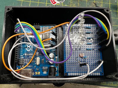
I got the laser and had a spot about 18 feet away that I could draw a line for it to follow, but the spot on the wall was pretty large - at least 5mm across. I felt that would decrease its accuracy and my eyesight would play a factor as the contrast from the bright spot made finding the center pretty challenging. I was pondering this when I realized I had an Arduino Uno laying around, so I created a little circuit board using a light depended resistor (LDR) and five LEDs and wrote some simple code for the Arduino that would change which LED lit up based on the intensity of the light received.
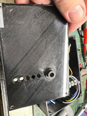
I 3D printed a box for it with a cover that had five holes for the LEDs and another for the LDR. The hole for the LDR is about 1.5mm across and I made adjustments to the sensitivity levels so the lights would not line up unless the center of the light spot was right over the hole. I have a little internal shield in there to prevent internal reflections in the box itself from affecting the readings. I also have some raised lines that I painted white to help me align it from across the room.
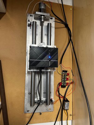
Satisfied with myself, I went to put it on the wall and realized that while it would be great if I never moved the mill head, it did nothing unless it could move as well and move accurately up and down. It was like the children's story of the old lady who swallowed a fly - I got a laser but that sent me to design a circuit and write some code and once that was done I realized I needed something to raise and lower the whole device to get it into the new position of the laser. I used a cheap 12VDC motor, a 3D printer leadscrew, and some fairly cheap linear rails to mount the whole thing to a scrap aluminum plate I had laying around. I installed limit switches at each end and ran a toggle switch over to the mill.
The motor was too slow at 12VDC so I opted to supply 18VDC to speed things up. I figured the duty cycle will be very low so this should not be an issue and if it is the motor cost like $13 so I can just replace it. To power the Arduino I happened to have a buck converter left over from another project so it is powered from the same supply that runs the motor.
I set the code to have the first light on whenever the Arduino has power. This is just to tell me it is plugged in as I could see myself running the thing up and down cursing as to why I can't get it to give me all five lights. Aligning it on the wall was an iterative process. I milled a hole in some aluminum with the mill at its lowest point and the quill as far up as possible. I set the rail/detector system to read at all five lights at that point and then moved the mill head up as far as I could for the quill to reach the hole again and adjusted the upper part. I milled some slots in the backer plate to facilitate this but it took at least 30 minutes to get something that I was satisfied with. The images of the device on the wall shows one image with just the one light on and another when the laser is on which shows all five. The toggle switch is just to the right of the laser and the toggle clamp is how I turn it on and off. The laser is rechargeable and has a USB Type A plug under the cap. Leaving the laser on for several minutes kills the battery so I will be soldering up a customer connector to keep 5V on the laser. The way I set the intensity it needs to be at full strength as the hole is small and even when right on the spot if the laser is not putting out full power the detection limits are too low.
Anyway, it "works". After moving the head the detector is pretty sensitive to misalignment. To get all five lights on I have to give small taps to the head in one direction or another to get the lit up. When aligned the tool slides right back into the hole. I also have to tighten the head bolts carefully and in steps as the act of tightening the bolts takes it a bit out of alignment. I sure wish there was a better way to clamp the head around the column, but I guess that is what knee mills are for.
I would be interested in other methods folks use to check the X as I am sure there is a better way to do this than how I did it.
The one thing I know for sure is that putting all of this together, while fun, is probably one of the most ridiculous projects I have done. I have my doubts as to how accurate it will ultimately be, but I am not making stuff for NASA and just getting out the wobbler and resetting my origins with the DRO will probably be just as fast as the process I created here. Once I was deep into the project I had to finish it (I still have some cable management to finish up).
There you have it - my contribution to the long list of "keeping the X" solutions!
Tom
I got the laser and had a spot about 18 feet away that I could draw a line for it to follow, but the spot on the wall was pretty large - at least 5mm across. I felt that would decrease its accuracy and my eyesight would play a factor as the contrast from the bright spot made finding the center pretty challenging. I was pondering this when I realized I had an Arduino Uno laying around, so I created a little circuit board using a light depended resistor (LDR) and five LEDs and wrote some simple code for the Arduino that would change which LED lit up based on the intensity of the light received.
I 3D printed a box for it with a cover that had five holes for the LEDs and another for the LDR. The hole for the LDR is about 1.5mm across and I made adjustments to the sensitivity levels so the lights would not line up unless the center of the light spot was right over the hole. I have a little internal shield in there to prevent internal reflections in the box itself from affecting the readings. I also have some raised lines that I painted white to help me align it from across the room.
Satisfied with myself, I went to put it on the wall and realized that while it would be great if I never moved the mill head, it did nothing unless it could move as well and move accurately up and down. It was like the children's story of the old lady who swallowed a fly - I got a laser but that sent me to design a circuit and write some code and once that was done I realized I needed something to raise and lower the whole device to get it into the new position of the laser. I used a cheap 12VDC motor, a 3D printer leadscrew, and some fairly cheap linear rails to mount the whole thing to a scrap aluminum plate I had laying around. I installed limit switches at each end and ran a toggle switch over to the mill.
The motor was too slow at 12VDC so I opted to supply 18VDC to speed things up. I figured the duty cycle will be very low so this should not be an issue and if it is the motor cost like $13 so I can just replace it. To power the Arduino I happened to have a buck converter left over from another project so it is powered from the same supply that runs the motor.
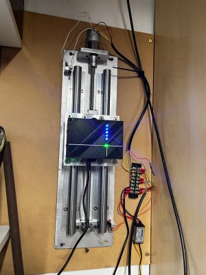
I set the code to have the first light on whenever the Arduino has power. This is just to tell me it is plugged in as I could see myself running the thing up and down cursing as to why I can't get it to give me all five lights. Aligning it on the wall was an iterative process. I milled a hole in some aluminum with the mill at its lowest point and the quill as far up as possible. I set the rail/detector system to read at all five lights at that point and then moved the mill head up as far as I could for the quill to reach the hole again and adjusted the upper part. I milled some slots in the backer plate to facilitate this but it took at least 30 minutes to get something that I was satisfied with. The images of the device on the wall shows one image with just the one light on and another when the laser is on which shows all five. The toggle switch is just to the right of the laser and the toggle clamp is how I turn it on and off. The laser is rechargeable and has a USB Type A plug under the cap. Leaving the laser on for several minutes kills the battery so I will be soldering up a customer connector to keep 5V on the laser. The way I set the intensity it needs to be at full strength as the hole is small and even when right on the spot if the laser is not putting out full power the detection limits are too low.
Anyway, it "works". After moving the head the detector is pretty sensitive to misalignment. To get all five lights on I have to give small taps to the head in one direction or another to get the lit up. When aligned the tool slides right back into the hole. I also have to tighten the head bolts carefully and in steps as the act of tightening the bolts takes it a bit out of alignment. I sure wish there was a better way to clamp the head around the column, but I guess that is what knee mills are for.
I would be interested in other methods folks use to check the X as I am sure there is a better way to do this than how I did it.
The one thing I know for sure is that putting all of this together, while fun, is probably one of the most ridiculous projects I have done. I have my doubts as to how accurate it will ultimately be, but I am not making stuff for NASA and just getting out the wobbler and resetting my origins with the DRO will probably be just as fast as the process I created here. Once I was deep into the project I had to finish it (I still have some cable management to finish up).
There you have it - my contribution to the long list of "keeping the X" solutions!
Tom
Attachments

Last edited: