- Joined
- Feb 8, 2014
- Messages
- 11,144
I can only show bits & pieces of this one. I can't show the proprietary parts or discuss the purpose. But there will be some interesting machining and work holding solutions for the parts I can show.
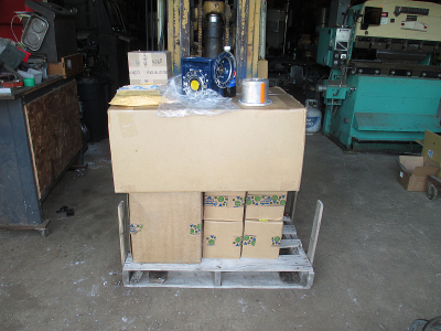
The pallet full of stuff that is going into this project
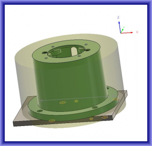
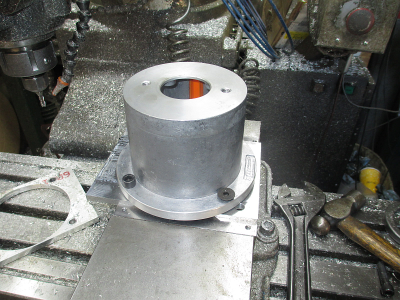
This is the part I've been working on for the last couple of days. A spacer to mount a hollow shaft gearbox to a machine frame. OK, maybe more like a day in real time, but I'm old & worn out and can only work in the shop 4 or 5 hours a day, and then not too hard. I'm glad I have a CNC machine, it does most of the work. If I had to turn cranks for 8 hours, I couldn't do it.
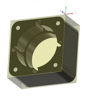
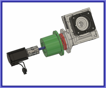
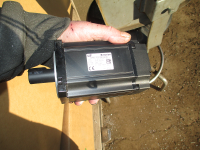
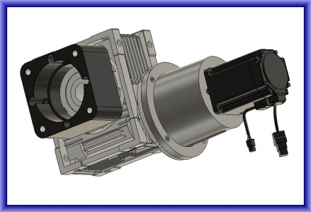
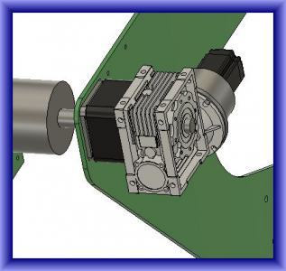
It goes in this assembly. The motor mount and motor are a bit unconventional in this application. I'm using a 750W servo motor (basically a NEMA 34 size, tiny little thing) to drive the gearbox rather than a conventional NEMA 56C frame motor that it is designed for. The little servo motor and drive was actually less expensive than the 56C wash down motor and VFD that I would have used, and has much better torque characteristics than a standard 3 phase motor, and it's wash down rated. Using a hydraulic pump/motor adapter, installed backwards, to connect the motor to the gearbox. Going to need to modify the adapter a bit also. But for the $30 the adapter cost, I couldn't build one. Just the material for it would have cost that much or more.
The work piece started out life as a 6.5 x 6.5 x 12'' chunk of aluminum, then I sawed that down to 5.5 x 5.5 x 3.125''. The local metal supplier had a bunch of these drops on the shelf.
Then the question of how to hang onto it for efficient machining. I need to machine all six sides of the part as well as the ID and I don't want to do multiple setups. So one possibility is to cut the raw stock a bit thick and machine dovetails in both the part and the vice jaws. The dove tails would allow holding the part with minimum grip height and allow work on 5 sides of the part in one setup. Then for the last operation just flip it over and face off to the proper thickness.
A note on vice jaws, I don't even own a set of hard jaws for my Kurt vises, we just make mild steel or aluminum soft jaws as needed. And if they need machining for fixturing a job then you can always make new ones when needed. We usually make a half dozen or so sets at a time. Also much easier on tools than hard jaws when you run that endmill or drill bit into them.
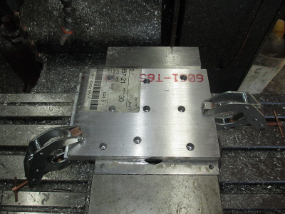
The alternative is to use a fixture plate that you could bolt to the table or hold in the vise, which is what I did in this case. But I still cut a dovetail on the vice jaws, the jaws in this case are mild steel.
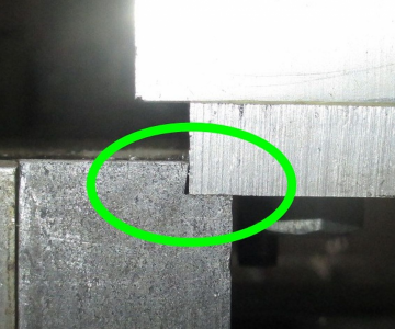
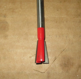
Using this 14° dovetail router bit. I wanted the sharp edge to catch the fixture plate so it could not pull out of the vise jaws. I could have cut a mating dovetail on the plate also, but I really didn't think I would need it. The fixture plate is a piece of 3/8 thick aluminum.
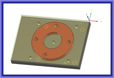
First I drilled & tapped the back side of the work piece and also drilled a couple of dowel pin holes, I reamed these at 0.251'' for a slip fit on the dowel pins.
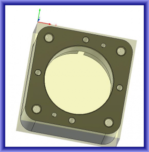
Then put the fixture plate in the vise and drilled the mounting holes, and reamed the dowel pin holes at 0.2495'' for a tight fit on the dowel pins. The work X0, Y0 was also established at the upper right corner in this operation and will remain there until the job is complete. I was a bit worried about the 3/8 plate bowing from vice pressure, then I realized it is not going anywhere when I screw that 3 inch thick chunk to it.
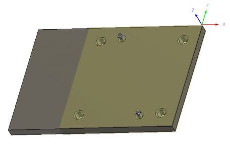
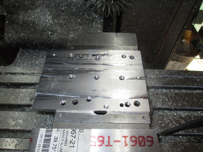
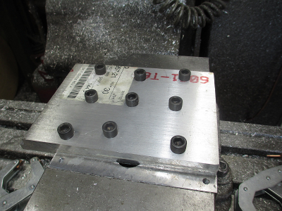
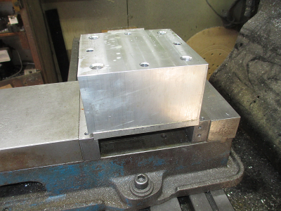
Then just mount the work onto the fixture plate, locating on the dowel pins and bolt in from the bottom. Then drill & tap the mounting holes on the top side.
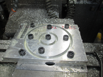
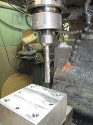
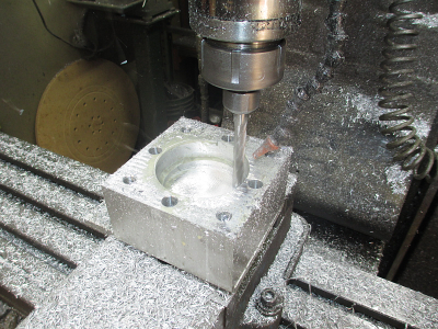
That end mill is a bit long, I don't like that much stick out, but I need to reach 3 inches deep, and it's the only long end mill around that size that I had. A 4 flute is not the best for aluminum, a 3 flute aluminum cutting carbide would have been better. Ya gotta do what ya gotta do.
And making chips
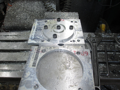
And finished, well almost.......
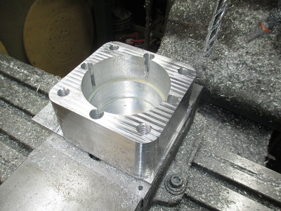
I measured the bores and was way undersize.... HUH? Like about 50 thou undersize, and the outside is oversize by the same amount. OK, go back and check the drawing..... Nope, drawing is correct. Look at the Stock to Leave in the CAM setup.... Nope, it's correctly set at zero. The only thing left is the 1/2'' end mill is undersize. YUP, only it's not a 1/2'' end mill, it's actually 12mm (~0.475''). I had no idea I had one of those.
  I normally check the endmill for actual size when setting up the CAM, but this one was new out of the box and looked to be high quality so I just expected it to be on size. No big problem, back into the CAM setup and plug in the actual size and run the finishing again passes tomorrow. At least they are under size, I can fix that pretty easy. Had they been over size I would have been building a new one.
The pallet full of stuff that is going into this project

This is the part I've been working on for the last couple of days. A spacer to mount a hollow shaft gearbox to a machine frame. OK, maybe more like a day in real time, but I'm old & worn out and can only work in the shop 4 or 5 hours a day, and then not too hard. I'm glad I have a CNC machine, it does most of the work. If I had to turn cranks for 8 hours, I couldn't do it.


It goes in this assembly. The motor mount and motor are a bit unconventional in this application. I'm using a 750W servo motor (basically a NEMA 34 size, tiny little thing) to drive the gearbox rather than a conventional NEMA 56C frame motor that it is designed for. The little servo motor and drive was actually less expensive than the 56C wash down motor and VFD that I would have used, and has much better torque characteristics than a standard 3 phase motor, and it's wash down rated. Using a hydraulic pump/motor adapter, installed backwards, to connect the motor to the gearbox. Going to need to modify the adapter a bit also. But for the $30 the adapter cost, I couldn't build one. Just the material for it would have cost that much or more.


The work piece started out life as a 6.5 x 6.5 x 12'' chunk of aluminum, then I sawed that down to 5.5 x 5.5 x 3.125''. The local metal supplier had a bunch of these drops on the shelf.
Then the question of how to hang onto it for efficient machining. I need to machine all six sides of the part as well as the ID and I don't want to do multiple setups. So one possibility is to cut the raw stock a bit thick and machine dovetails in both the part and the vice jaws. The dove tails would allow holding the part with minimum grip height and allow work on 5 sides of the part in one setup. Then for the last operation just flip it over and face off to the proper thickness.
A note on vice jaws, I don't even own a set of hard jaws for my Kurt vises, we just make mild steel or aluminum soft jaws as needed. And if they need machining for fixturing a job then you can always make new ones when needed. We usually make a half dozen or so sets at a time. Also much easier on tools than hard jaws when you run that endmill or drill bit into them.
The alternative is to use a fixture plate that you could bolt to the table or hold in the vise, which is what I did in this case. But I still cut a dovetail on the vice jaws, the jaws in this case are mild steel.

Using this 14° dovetail router bit. I wanted the sharp edge to catch the fixture plate so it could not pull out of the vise jaws. I could have cut a mating dovetail on the plate also, but I really didn't think I would need it. The fixture plate is a piece of 3/8 thick aluminum.

First I drilled & tapped the back side of the work piece and also drilled a couple of dowel pin holes, I reamed these at 0.251'' for a slip fit on the dowel pins.

Then put the fixture plate in the vise and drilled the mounting holes, and reamed the dowel pin holes at 0.2495'' for a tight fit on the dowel pins. The work X0, Y0 was also established at the upper right corner in this operation and will remain there until the job is complete. I was a bit worried about the 3/8 plate bowing from vice pressure, then I realized it is not going anywhere when I screw that 3 inch thick chunk to it.

Then just mount the work onto the fixture plate, locating on the dowel pins and bolt in from the bottom. Then drill & tap the mounting holes on the top side.

That end mill is a bit long, I don't like that much stick out, but I need to reach 3 inches deep, and it's the only long end mill around that size that I had. A 4 flute is not the best for aluminum, a 3 flute aluminum cutting carbide would have been better. Ya gotta do what ya gotta do.

And making chips

And finished, well almost.......

I measured the bores and was way undersize.... HUH?
 Like about 50 thou undersize, and the outside is oversize by the same amount. OK, go back and check the drawing..... Nope, drawing is correct. Look at the Stock to Leave in the CAM setup.... Nope, it's correctly set at zero. The only thing left is the 1/2'' end mill is undersize. YUP, only it's not a 1/2'' end mill, it's actually 12mm (~0.475''). I had no idea I had one of those.
Last edited:


 I have a small similar project I need to make if I ever get motivated enough to start it .
