-
Welcome back Guest! Did you know you can mentor other members here at H-M? If not, please check out our Relaunch of Hobby Machinist Mentoring Program!
You are using an out of date browser. It may not display this or other websites correctly.
You should upgrade or use an alternative browser.
You should upgrade or use an alternative browser.
My current project
- Thread starter JimDawson
- Start date
- Joined
- Feb 8, 2014
- Messages
- 11,144
Well I got the jog keys figured out. About 200 lines of code and 6 hours later they seem to work fine. Turns out the key press capture method I was using doesn't play nice with a 64 bit system. So I had to rewrite all of the code for that functionality. Once I got the logic figured out for one key, the rest was pretty much copy & paste (and debug). I also cleaned up a couple of other small issues that had been bothering me in that area.
When you are programming for real time machine control, you have to try to anticipate every possible issue that could crash a machine or cause something else that could horribly go wrong and find a bulletproof solution to eliminate the possibility. It's not like writing an accounting application or something where the worst that happens is you get bad data out.
I got some pictures of the finished parts I completed yesterday.
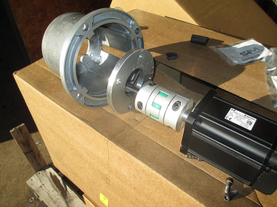
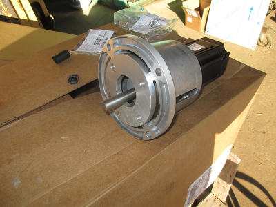
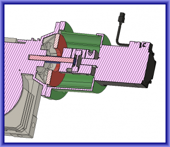
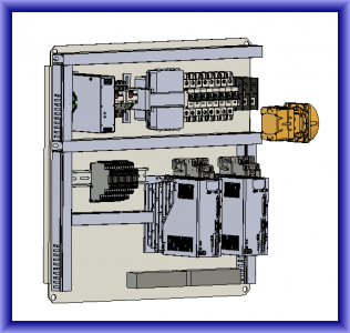
Now on to the electrical panel.... Stay tuned
When you are programming for real time machine control, you have to try to anticipate every possible issue that could crash a machine or cause something else that could horribly go wrong and find a bulletproof solution to eliminate the possibility. It's not like writing an accounting application or something where the worst that happens is you get bad data out.
I got some pictures of the finished parts I completed yesterday.


Now on to the electrical panel.... Stay tuned

Last edited:
- Joined
- Feb 8, 2014
- Messages
- 11,144
The DMM software could have a few more knobs to twiddle. Might make for easier manual tuning. I'm still trying to understand the relationship of the on screen parameters when operating in analog speed or torque mode. The documentation is not clear on this subject. I have never tried operating in analog speed mode, but have used torque mode in a couple of different applications. Most notably my lathe. But I have never had the time to really go in and play with the parameters to see what effect they have on the operation.IMO the main weak link for the DMM is the PC software. I could expound but I'm sure I don't need to. Reading through the RS485 section of the manual makes me think the drives are capable of a lot more than the software makes available to you.
Please let me/us know how the commissioning of the new LS servos goes compared to what's been discussed so far. I have been eyeballing those pretty hard but I don't have a good (enough) excuse to buy one yet.
I have the control panel complete and the LS motors drives commissioned. Took me about a day to get the first one to turn. This was not a documentation issue, but rather my failure at reading comprehension. The Quick Start documentation is written in very clear English with step by step instructions. I just managed to skip a few bits of it.

The setup software has both a wizard driven quick setup for the most common functions and a very comprehensive tabbed manual entry spreadsheet like interface, probably around 500 or so parameters available to the user. The main user manual is a very good translation from Korean, and very readable. The Quick Start guide was written by a native English speaker, most likely by one of the techs at Automation Direct.
I'm operating these motors just like a 3 phase motor and a VFD with a pot. No positioning required. I chose to use servos because of their low speed torque abilities and power density, as well as their relatively low cost. I'll be running one motor up to about 1800 RPM, and the other up to about 60 RPM.
The second motor took about 10 minutes to setup and that included the wait time for Windows to finish updating and a mandatory reboot. $&%#%^ Microsoft.
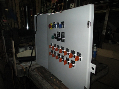
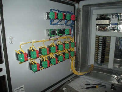
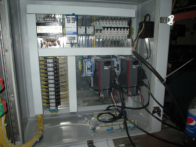
- Joined
- Feb 8, 2014
- Messages
- 11,144
Thank you.Now THAT is clean wiring!
Brian
- Joined
- Feb 8, 2014
- Messages
- 11,144
OK, for the next little piece of the puzzle, I made this little yoke. Overall not a very interesting part, but required some work holding thought.
I need to machine all 6 sides of the cube, so how to do that in the most efficient manor and still be able to hang onto the part. The final part is about 2'' x 1.625'' x 1''.
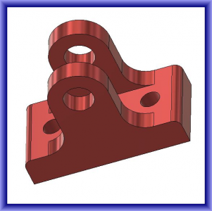
So start with a 2 1/4 x 1 3/4 x 1 1/4 piece to make sure you have material to remove all the way around. I normally leave at least 1/8 inch all the way around so I don't come up short.
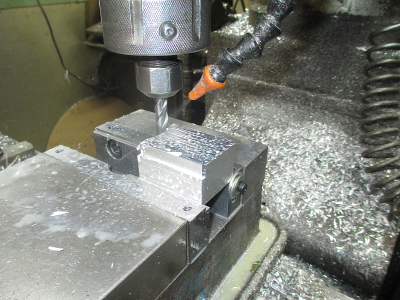
Profile the outside to 1.030 depth. This is 0.030'' deeper that the final width of the part. Allows a burr free cleanup on the other side. This also leaves about 1/4 inch of material in the vice to hang onto the part. As noted in a previous post above I have a 14° dovetail cut on the vice jaws, really hangs onto the part.
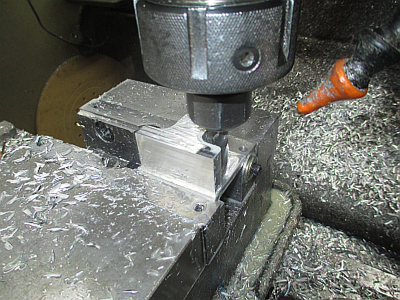
Once that operation is complete, drill & ream the 0.375 hole.
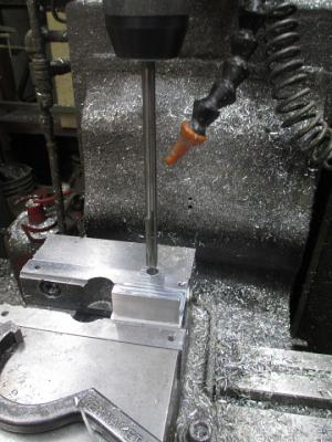
Now flip the part over and face off the excess material.
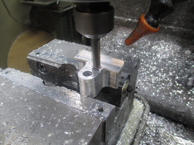
Then flip the part up and machine the slot. In all cases machining was done with a 3/8'' 3 flute aluminum cutting carbide end mill, about 2500 RPM, 10 IPM feed, tooth load about 0.0015'', 0.375'' stepdown, 0.150'' stepover/pass, using a trochoidal cutting strategy for efficient tool loading. X and Y zero were set at the vice stop for the entire job, only the Z zero changed as needed. Total spindle time was about 35 minutes. (and about 3 hours of setup and CAM time) Thinking through the entire process before ever making a chip saves a lot of time in the end and you don't paint yourself into a corner.
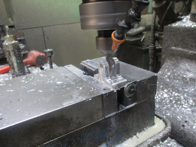
Drill the two 1/4'' mounting holes and done.
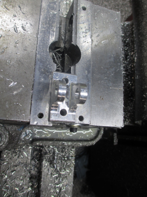
I need to machine all 6 sides of the cube, so how to do that in the most efficient manor and still be able to hang onto the part. The final part is about 2'' x 1.625'' x 1''.

So start with a 2 1/4 x 1 3/4 x 1 1/4 piece to make sure you have material to remove all the way around. I normally leave at least 1/8 inch all the way around so I don't come up short.

Profile the outside to 1.030 depth. This is 0.030'' deeper that the final width of the part. Allows a burr free cleanup on the other side. This also leaves about 1/4 inch of material in the vice to hang onto the part. As noted in a previous post above I have a 14° dovetail cut on the vice jaws, really hangs onto the part.

Once that operation is complete, drill & ream the 0.375 hole.

Now flip the part over and face off the excess material.

Then flip the part up and machine the slot. In all cases machining was done with a 3/8'' 3 flute aluminum cutting carbide end mill, about 2500 RPM, 10 IPM feed, tooth load about 0.0015'', 0.375'' stepdown, 0.150'' stepover/pass, using a trochoidal cutting strategy for efficient tool loading. X and Y zero were set at the vice stop for the entire job, only the Z zero changed as needed. Total spindle time was about 35 minutes. (and about 3 hours of setup and CAM time)

Drill the two 1/4'' mounting holes and done.


