- Joined
- Apr 5, 2011
- Messages
- 121
Well I finished my Studebaker restoration, my machine shop overhaul, and now it was time to try out my South Bend lathe to see if I have to make any adjustments etc., so time to make some chips.
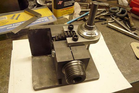
I had been looking at dividing heads and rotary tables for several years now ever since I cut a gear using a spin index which has very limited dividing capabilities. Dividing heads are pretty pricey so started looking for ideas to build one on the net. I found lots of them there but one really caught my interest. <http://www.members.shaw.ca/me.walsh/dividing.htm>. I fell in love with that idea so decided that was what I was going to build. I made a drawing of how I would build it and took it to a local foundry for a price on casting the body. He said if I made the pattern and all they had to do was cast it, it would just be labor plus material, less than $50.00. So I created the pattern and brought it back to him and 4 days later I picked up two castings. One was real nice and the other one a bit rough with some pockets in the surface mainly on the top where the sprue and risers had been.
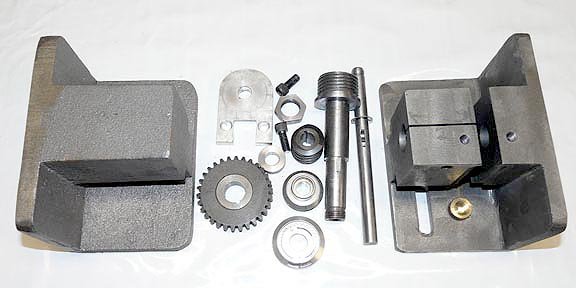
Here are most of the parts as we made them including the extra casting on the left.
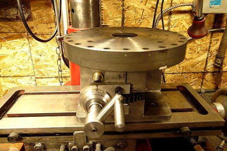
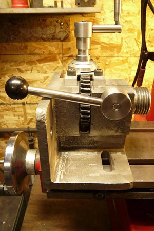
I decided to start with the rough casting and if I screwed it up I would still have the good one to fall back on. Here is what we ended up with.
The following is description of how we built it
We had to find a way to hold the casting on the mill and finally decided our best option was an angle plate clamped to the table on the mill.
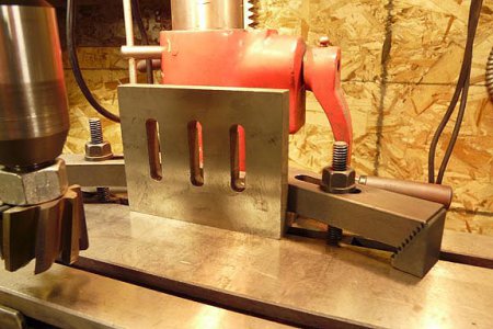
The first surface to be milled was the rough back side where the metal had been poured in. We clamped it to the angle plate with 4 vice grip C clamps and using a shell end mill with arbor made from a 3/4" bolt (not perfect) but it worked we took a huge layer off the top. We then turned it over and milled the face of the nose parallel to the back. It did leave a few of the pockets but nothing that would bother it in use. We repeated this process with the bottom side and verified that we were square with the two surfaces and then machined the top flat. Since it was rather rough on most surfaces of this casting we continued to do the same on all surfaces we could reach with the shell end mill and the hollows on the sides were trimmed out with an extra long 1/2" centre cutting 4 flute end mill.
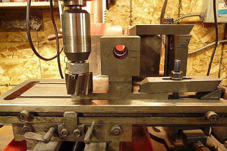
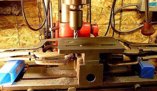
Although the slots were cut in the base later in the process we show it here to illustrate how we clamped the casting to the angle plate to start the process.
The next job was to get the slot cut for the worm gear to fit into. This was to be 9/16" wide. I decided that the best method would be with a horizontal mill which I did not have. I did have a 6" x 3/16" cotter with 1" bore which probably would just reach to the bottom of the slot or close to it. I drilled a 9/16" cross hole at the bottom of the slot just above the recess in the sides. I took the cutter to a friend who runs a small machine shop in town who was able to cut it for me.
I will do an article on him some time in the future as he will be celebrating the 100 th. anniversary of his family shop on May 23, 2014. His father started this shop 100 years ago and serviced the oil industry in the area ever since. Albert, although he too should be retired still makes the brass barrels and leather cups used to draw the oil up in the oil well. This area is the birth place of the oil industry where the first oil production was started in North America. An other story in itself.
Once the slot was cut I could bore out the casting for the spindle. We had a small tail stock that we would be using with this dividing head when we required it so set them both on the mill table and with a centre in the tail stock we gave it a light swat with a dead blow hammer to mark the centre where the bore had to go. We centre drilled it and then mounted it on the face plate on my lathe after having taken a skim cut off the face plate to make sure it was going to run true. Then using two mill clamps and the tail stock centre to line it up we through drilled it with a 1/4" drill bit and progressively enlarged it to 3/4", the diameter the spindle would be for the back half. The front half was bored with a bar to 7/8" although we had intended to make it 1", but when we made the spindle we ended up just under that so finished it to 7/8". This was done with the slowest back gear.
The reason for the step was that the gear would have to be engaged with a woodruff key and the key would have to be able to pass through the front part of the bore.
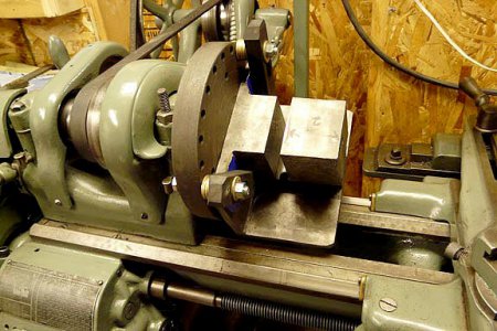
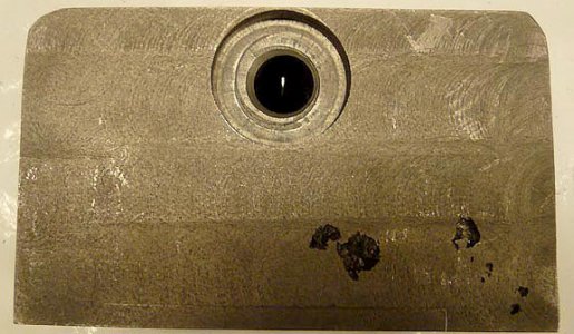
After this the back was counter bored to accommodate a nut on the spindle using a small boring head in the mill.
The spindle was first rough turned to shape and then bored to 1/2" and reamed to a #2 Morse taper. This was started by hand with a square wrench and once started we ran the lathe in back gear again and using the tail stock to apply a light pressure and the wrench resting on the carriage we gently continued the reaming using lots of oil and frequently clearing out the chips.
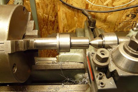
Once the reaming was finished we inserted a taper shank with a straight end on it and with that supported in the TS centre finished the nose of the spindle including 1 1/2 - 8 thread to match the SB lathe. Then the spindle was reversed and the other end machined gripping it by the tapered shank end. We had the slot for the gear in the casting cut 2" from the face so the first cut was to exact 7/8". Now we could cut the remainder to 3/4" up to the 2" mark. The last part, enough for a thin 11/16" NF nut was turned to that diameter. This would keep the spindle from pulling forward.
The next job was slit the casting through the top for the front half so we could clamp the spindle tight when in use.
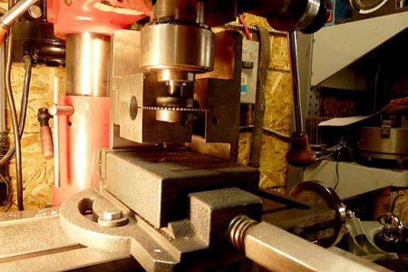
This was followed by a test fit of the parts made so far and to check our match to the tail stock. We found we needed to cut some clearance for the worm around the gear as shown.
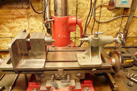
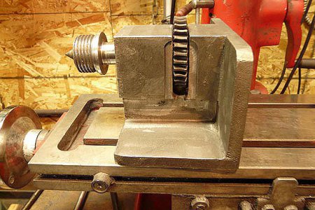
The next step was to create the plate on top to support the worm shaft. After making a card stock template with a 1/2" hole punched in it and the shaft with the worm held in contact with the gear we drew out where the recess for the gear needed to be as well as the arc for the dial. After cutting the arc with the band saw and finishing it on the disc sander we then clamped the plate in an upside down small drill press vice and trimmed out the recess for the gear on the table saw. We then determined where the cap screws should go and drilled the holes in the plate. We then again slipped the plate over the shaft with the worm meshed with the gear and marked the casting through the holes with a transfer punch in the plate and drilled them for 1/4" - 20 and tapped the holes. The holes in the plate where then slightly enlarged to allow for adjusting the plate for alignment purposes.
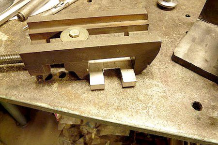
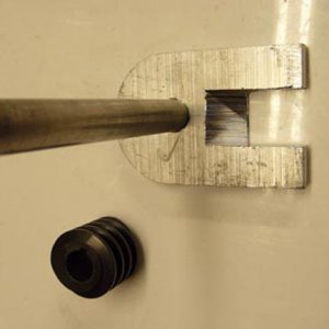
We then used a transfer punch to mark the casting for the bottom of the worm shaft and drilled a 1/2" pocket hole for the shaft to sit in. We found the shaft was binding so we drilled it out to 11/16" and made a brass slug to press in the hole. We then use the extra long 1/2" end mill and inserted it through the plate and bored the hole in the brass that way which worked well. We also formed a bit of a ball on the end of the worm shaft which also alleviated more binding and made for smoother turning. Note a C clip holds the worm up and an exact spacer is between the plate and the worm to eliminate any back lash.
Note. Both this shaft and the spindle received a 1/8" by 1/2" woodruff key for the gears.
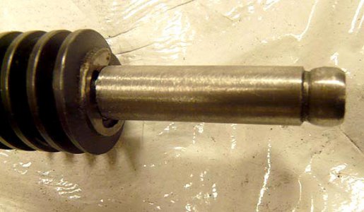
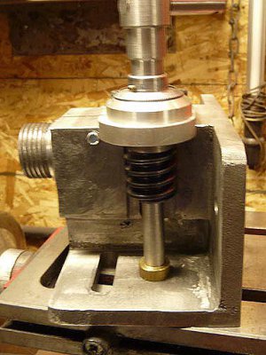
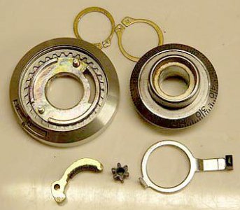
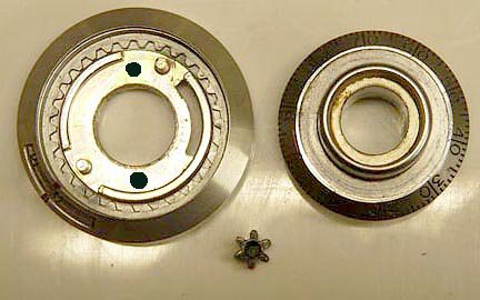
Next comes the fitting of the dial. This is a 15 turn dial which has 100 graduations and a 15 turn counter as well as a brake. We disassembled it by removing the 2 snap rings from the bottom. It has a 1/2" bushing and a small set screw holding the plastic knob. There was a web in the centre of the bushing which would have engaged a radio shaft so we had to carefully drill that out to 1/2". The knob and brake parts we discarded. We just used the base and the small gear which operates the turn counter and the dial with the set screw. We drilled two small holes in the base where they wouldn't interfere with the counter and transferred these to the aluminum plate for #4-40 screws to secure it. We then marked the shaft for a dimple to lock the tiny set screw in.
We then finished up by making the crank to suit and secured it with a set screw in a dimple on the shaft.
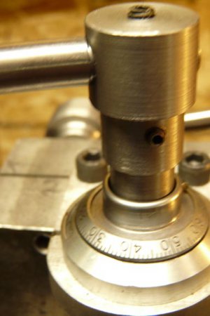
The final step was to drill a cross hole through above the spindle for 5/16" NC. The side where the worm is was threaded the other side got drilled to 5/16" and a piece of threaded rod was used for the clamp with a lock nut on the threaded side. This allows for adjustment to orientate the lock handle so it can rotate in the right arc to tighten.

The worm and gear are the equivalent to Boston Gear #G11051RH and G1056RH with a 30-1 ratio. If anyone has questions about this feel free to contact me about it. The gear was 1/2" bore so we chucked it up by it's hub and bored it to 3/4" and then parted it off. We then had to broach a 1/8" keyway in it.
Hope you enjoyed this journey that took up some of my time these past two weeks.
Nick




I had been looking at dividing heads and rotary tables for several years now ever since I cut a gear using a spin index which has very limited dividing capabilities. Dividing heads are pretty pricey so started looking for ideas to build one on the net. I found lots of them there but one really caught my interest. <http://www.members.shaw.ca/me.walsh/dividing.htm>. I fell in love with that idea so decided that was what I was going to build. I made a drawing of how I would build it and took it to a local foundry for a price on casting the body. He said if I made the pattern and all they had to do was cast it, it would just be labor plus material, less than $50.00. So I created the pattern and brought it back to him and 4 days later I picked up two castings. One was real nice and the other one a bit rough with some pockets in the surface mainly on the top where the sprue and risers had been.
Here are most of the parts as we made them including the extra casting on the left.

I decided to start with the rough casting and if I screwed it up I would still have the good one to fall back on. Here is what we ended up with.


The following is description of how we built it
We had to find a way to hold the casting on the mill and finally decided our best option was an angle plate clamped to the table on the mill.

The first surface to be milled was the rough back side where the metal had been poured in. We clamped it to the angle plate with 4 vice grip C clamps and using a shell end mill with arbor made from a 3/4" bolt (not perfect) but it worked we took a huge layer off the top. We then turned it over and milled the face of the nose parallel to the back. It did leave a few of the pockets but nothing that would bother it in use. We repeated this process with the bottom side and verified that we were square with the two surfaces and then machined the top flat. Since it was rather rough on most surfaces of this casting we continued to do the same on all surfaces we could reach with the shell end mill and the hollows on the sides were trimmed out with an extra long 1/2" centre cutting 4 flute end mill.


Although the slots were cut in the base later in the process we show it here to illustrate how we clamped the casting to the angle plate to start the process.
The next job was to get the slot cut for the worm gear to fit into. This was to be 9/16" wide. I decided that the best method would be with a horizontal mill which I did not have. I did have a 6" x 3/16" cotter with 1" bore which probably would just reach to the bottom of the slot or close to it. I drilled a 9/16" cross hole at the bottom of the slot just above the recess in the sides. I took the cutter to a friend who runs a small machine shop in town who was able to cut it for me.
I will do an article on him some time in the future as he will be celebrating the 100 th. anniversary of his family shop on May 23, 2014. His father started this shop 100 years ago and serviced the oil industry in the area ever since. Albert, although he too should be retired still makes the brass barrels and leather cups used to draw the oil up in the oil well. This area is the birth place of the oil industry where the first oil production was started in North America. An other story in itself.
Once the slot was cut I could bore out the casting for the spindle. We had a small tail stock that we would be using with this dividing head when we required it so set them both on the mill table and with a centre in the tail stock we gave it a light swat with a dead blow hammer to mark the centre where the bore had to go. We centre drilled it and then mounted it on the face plate on my lathe after having taken a skim cut off the face plate to make sure it was going to run true. Then using two mill clamps and the tail stock centre to line it up we through drilled it with a 1/4" drill bit and progressively enlarged it to 3/4", the diameter the spindle would be for the back half. The front half was bored with a bar to 7/8" although we had intended to make it 1", but when we made the spindle we ended up just under that so finished it to 7/8". This was done with the slowest back gear.
The reason for the step was that the gear would have to be engaged with a woodruff key and the key would have to be able to pass through the front part of the bore.


After this the back was counter bored to accommodate a nut on the spindle using a small boring head in the mill.
The spindle was first rough turned to shape and then bored to 1/2" and reamed to a #2 Morse taper. This was started by hand with a square wrench and once started we ran the lathe in back gear again and using the tail stock to apply a light pressure and the wrench resting on the carriage we gently continued the reaming using lots of oil and frequently clearing out the chips.

Once the reaming was finished we inserted a taper shank with a straight end on it and with that supported in the TS centre finished the nose of the spindle including 1 1/2 - 8 thread to match the SB lathe. Then the spindle was reversed and the other end machined gripping it by the tapered shank end. We had the slot for the gear in the casting cut 2" from the face so the first cut was to exact 7/8". Now we could cut the remainder to 3/4" up to the 2" mark. The last part, enough for a thin 11/16" NF nut was turned to that diameter. This would keep the spindle from pulling forward.
The next job was slit the casting through the top for the front half so we could clamp the spindle tight when in use.

This was followed by a test fit of the parts made so far and to check our match to the tail stock. We found we needed to cut some clearance for the worm around the gear as shown.


The next step was to create the plate on top to support the worm shaft. After making a card stock template with a 1/2" hole punched in it and the shaft with the worm held in contact with the gear we drew out where the recess for the gear needed to be as well as the arc for the dial. After cutting the arc with the band saw and finishing it on the disc sander we then clamped the plate in an upside down small drill press vice and trimmed out the recess for the gear on the table saw. We then determined where the cap screws should go and drilled the holes in the plate. We then again slipped the plate over the shaft with the worm meshed with the gear and marked the casting through the holes with a transfer punch in the plate and drilled them for 1/4" - 20 and tapped the holes. The holes in the plate where then slightly enlarged to allow for adjusting the plate for alignment purposes.


We then used a transfer punch to mark the casting for the bottom of the worm shaft and drilled a 1/2" pocket hole for the shaft to sit in. We found the shaft was binding so we drilled it out to 11/16" and made a brass slug to press in the hole. We then use the extra long 1/2" end mill and inserted it through the plate and bored the hole in the brass that way which worked well. We also formed a bit of a ball on the end of the worm shaft which also alleviated more binding and made for smoother turning. Note a C clip holds the worm up and an exact spacer is between the plate and the worm to eliminate any back lash.
Note. Both this shaft and the spindle received a 1/8" by 1/2" woodruff key for the gears.


Next comes the fitting of the dial. This is a 15 turn dial which has 100 graduations and a 15 turn counter as well as a brake. We disassembled it by removing the 2 snap rings from the bottom. It has a 1/2" bushing and a small set screw holding the plastic knob. There was a web in the centre of the bushing which would have engaged a radio shaft so we had to carefully drill that out to 1/2". The knob and brake parts we discarded. We just used the base and the small gear which operates the turn counter and the dial with the set screw. We drilled two small holes in the base where they wouldn't interfere with the counter and transferred these to the aluminum plate for #4-40 screws to secure it. We then marked the shaft for a dimple to lock the tiny set screw in.


We then finished up by making the crank to suit and secured it with a set screw in a dimple on the shaft.

The final step was to drill a cross hole through above the spindle for 5/16" NC. The side where the worm is was threaded the other side got drilled to 5/16" and a piece of threaded rod was used for the clamp with a lock nut on the threaded side. This allows for adjustment to orientate the lock handle so it can rotate in the right arc to tighten.

The worm and gear are the equivalent to Boston Gear #G11051RH and G1056RH with a 30-1 ratio. If anyone has questions about this feel free to contact me about it. The gear was 1/2" bore so we chucked it up by it's hub and bored it to 3/4" and then parted it off. We then had to broach a 1/8" keyway in it.
Hope you enjoyed this journey that took up some of my time these past two weeks.
Nick


Last edited:

