- Joined
- Feb 1, 2015
- Messages
- 9,605
Thanks. I'm not sure I've got it 100%, but I'm getting there.
I plan to mail order a variety of these:
https://www.servocity.com/html/32_pitch_aluminum_hub_gears___.html
Along with some smaller brass pinion gears.
Just out of curiosity, I used a piece of string and a cardboard tube to visualize what 1 turn in ___ inches looks like. I'll need to reduce more than 80:1 to get the look I want with the spiral flutes. BTW the whole idea is for the kits sold by Woodcraft (minus a handle that is lathe turned by the customer). I got mom started and showed her to polish up the pieces for a shaving set for my brother. She did a great job, and the faux tortoise shell acrylic is so shiny, it looks like glass. He was super surprised and impressed. Now he and I plan to make some of the same kind of things. I think fake ivory would look great as a handle for a shaving brush, razor, and stem for the holder.
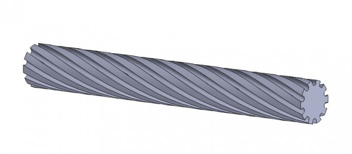
If I understand you correctly , you want to cut 10 equally spaced spirals with a pitch of 8/rev. using a Sherline milling machine and rotary table. Something like this:
You will have to synchronize the rotation of the rotary table to the axis screw in order to have a uniform pitch and uniform spacing. This can be done with a CNC mill with 4th axis capability. To do this properly, you will need stepper or servo motors on the rotary table and the x axis, as Jim Dawson has suggested.
There is another possibility which could be mechanically fairly complex. To get the required pitch with your .050" lead screw you need 8 x 20 = 160 turns of the lead screw for a full turn of the rotary table. If your rotary table has a 90:1 worm, the rotary table crank has to turn 90 times for one rotation so your lead screw will have to rotate 160/90 turns to rotate the table one full turn. If you set up a gear train with a ratio of 16:9, your rotary table will be properly synced. The change in direction of the drive train could be accomplished with a flexible rotary shaft. You will have to pay attention to backlash issues but you should be able to make your spiral.
To mount your rotary table in a vertical position a heavy angle plate can be implemented.
FYI, the drawing below has a pitch of 8"/rev. on a 1" cylinder.


