Need help with a VFD for my mill

Next question..Resistance Braking. If I am reading the manual correct I need a 35 ohm resistor for the 2.2kw drive. My question is what is the correct wattage? IIRC I read , or someone mentioned to me 350- 500 watt.

We have a few machines here at work that have resistors from this place.

http://www.surplussales.com/Resistors/WireWound/WW30-499.html

We have one on a 1hp 3 ph hitachi drive but there is no wattage written on the part just the ohms.

I was looking at this model: (RWM) 26-136-35R $25.00 seems like a good price to me.

- - - Updated - - -

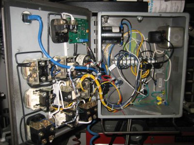
Bill Thanks for the wiring pictures of the tach.! They are very helpful!!


I must be missing something. Why do you need a braking resistor? I have 3 VFD's and not one has a resistor. You can control how fast you want the motor to wind down or speed up with the controller. So why the resister?
Warren
 
I must be missing something. Why do you need a braking resistor? I have 3 VFD's and not one has a resistor. You can control how fast you want the motor to wind down or speed up with the controller. So why the resister?
Warren

Depends on the rotating mass and how fast you want to stop it. I have 1 that doesn't need braking at all, 1 that does but I don't have a resistor so I set it to wind down longer and just wait, and 1 on a lathe that requires a resistor so I can stop a 10" chuck from 2000 rpm in 1.8 seconds. It all depends!
 
I mainly want the resistor for tapping, and to take the wear off of the built in resistor in the drive.

Sent from my SCH-I535 using Tapatalk
 
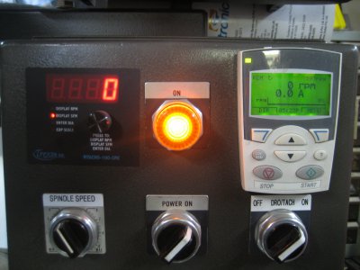
Night shift in post #4. The picture of your control panel. Is that the tachulator in the upper left corner? What is in the upper right corner?

Sent from my SCH-I535 using Tapatalk
 
Night shift in post #4. The picture of your control panel. Is that the tachulator in the upper left corner? What is in the upper right corner?
Hey Brian, yes the top left is the Tachulator. When I ordered it, I told them I did not want the alum box they provide with the face decal since I was installing in a control panel. They send me the stick on face panel so I could put it on once I cut the holes in the box.

On the top right is the remote display panel for the ABB VFD. Its connected to the VFD via a Cat 5 cable. The VFD is mounted in it's own box on the lower rear side of the pedistal to keep it out of the way. The remote panel allows me to change the program settings if I ever needed to (I haven't touched it since I initially installed it years ago). Bill

IMG_4339.JPG
 
Will this pot have the low r.p.m. control you mentioned?

Sent from my SCH-I535 using Tapatalk

No - this one is a linear pot, meaning that the resistance (and resulting output voltage) should change about the same amount per degree of rotation across the entire rotation, so the speed rate of change should be pretty much the same at either end of the rotation. I would start with a linear taper - if you want to make one end or the other less sensitive, it can be done by adding a fixed resistor from the center terminal to one end or the other. If fact, you could add a three position switch and a single fixed resistor that would allow you have three different rates of change very easily with this same pot, if you wanted to.
 
Hey Brian, yes the top left is the Tachulator. When I ordered it, I told them I did not want the alum box they provide with the face decal since I was installing in a control panel. They send me the stick on face panel so I could put it on once I cut the holes in the box.

On the top right is the remote display panel for the ABB VFD. Its connected to the VFD via a Cat 5 cable. The VFD is mounted in it's own box on the lower rear side of the pedistal to keep it out of the way. The remote panel allows me to change the program settings if I ever needed to (I haven't touched it since I initially installed it years ago). Bill

Great looking panel - Nice work!
 
O.K. Bill here is another question. What type of transformer did you use to power your tachulator? How about one of these?

http://www.ebay.com/itm/AC-110V-220...ch-Power-Supply-Convert-Adapter-/400563914329

- - - Updated - - -

No - this one is a linear pot, meaning that the resistance (and resulting output voltage) should change about the same amount per degree of rotation across the entire rotation, so the speed rate of change should be pretty much the same at either end of the rotation. I would start with a linear taper - if you want to make one end or the other less sensitive, it can be done by adding a fixed resistor from the center terminal to one end or the other. If fact, you could add a three position switch and a single fixed resistor that would allow you have three different rates of change very easily with this same pot, if you wanted to.


Dan this pot and resistor setup sounds great! Would you mind elaborating on the proper resistor needed, and how the wiring is configured?
 
Bill,

Nice work! Are you a machinist or a machine maintenance technician?

Harvey
(A CNC tech many years ago.)
 
Back
Top