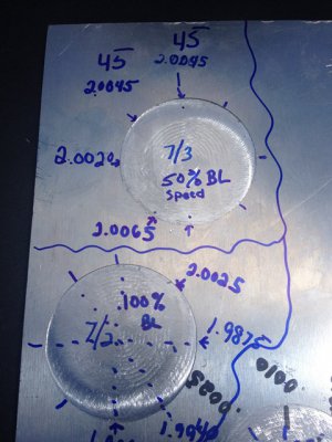
Newb, Mach3, backlash comp only works 50% speed.

countryguy

Active User
Registered
Joined
May 7, 2014
Messages
776
Sometimes as a newb I get too involved with the C part of Cnc. The cool screens, the DRO read outs, and stepper chattering away....... Cool but I had an experience I will post partly as a mach3 tip into the archives of time here.
Trust but verify! Pull out the Gage's a 2nd 3rd time. I did not and it cost me.

If you are new to cnc and Mach3 you have probably seen the HOSS vids on youtube. A prolific. Cnc poster and guru. He has a cool backlash video which describes the process for setting the motor speed to 100% and moving quickly along into alignment.

The short story. I started at 50% motor speed. Backlash in and Gage's with DRO, and Mach3 steps all calibrated. We were pretty proud of ourselves! Then we played around did some other stuff, but the lure of a Mach3 setting was in my head. So I popped the setting to 100% because it is so easy to do. And then I just listened for the backlash comp sound. Very audible.
Days later went to do something and found my table all out of whack?

Found out quickly what I messed up ( since I rolled mach3 back with the built in rollback tool) and recalled the moor speed on backlash was tweaked from 50 to 100 %. Watching the stepper run the ballscrews I found it was staggering, making noise, trying to turn, maybe some . Fits and starts. But to the untrained ear (now trained) it was the issue.

I think Hoss has 40k hits on some of his vids. So backlash comp and motor speed may not work on 100%.

Cg. Another great day to go break something else and learn even more!
 
Mach 3 needs a lot of experimentation on behalf of the operator. I too tweaked the compensation settings but had a fairly easy time of it. The machine has less than a thou on all linear axis and I do believe the compensation speed is set at 95%. It seems to be working. I'll take a guess that smaller compensation values do not require as much speed compensation. One thing to realize is that manually entering DRO values and zeroing to that location does not seem to enable the backlash compensation feature. i.e. To verify the compensation, you need to actually cut a part or at least dry-run a G-code program. I've discovered that boring a circle and making a diamond shape with the tips tangent to the table borders are adequate geometries to verify component accuracy. I prefer to actually cut the part and measure the results.


BTW: Right now, I'm doing some 4th (rotary) axis setups and it took 1/2 day to get my head wrapped around the configuration settings and backlash compensation. I'm just about ready but need to figure-out one more thing related to rotary table speed. The table manually jogs/rotates at an adequate speed but when running a CAM program, it rotates way too slow. I suspect the issue is related to angular rotation speed vs. part surface speed. I'm hoping to dig into that today if time allows.


Ray
 
I had similar issues with LinuxCNC while using backlash comp (and this was with servos). It would not lose step, but would error out ("Following error"). Basically with backlash comp the motors have to do double time when you switch directions. At low speed they can keep up, but at high speeds the acceleration required is too much, and you lose step on stepper motors, or you just can't keep up with servos. Still it was a very useful feature before I had ballscrews.
 
BTW: Right now, I'm doing some 4th (rotary) axis setups and it took 1/2 day to get my head wrapped around the configuration settings and backlash compensation. I'm just about ready but need to figure-out one more thing related to rotary table speed. The table manually jogs/rotates at an adequate speed but when running a CAM program, it rotates way too slow. I suspect the issue is related to angular rotation speed vs. part surface speed. I'm hoping to dig into that today if time allows.


Ray[/QUOTE]


I haven’t tried this on my 4[SUP]th[/SUP] axis yet, but check out the inverse time feed rate function (G93). Here is a link that explains it way better than I can :)) http://www.eng-tips.com/viewthread.cfm?qid=200454

My mistake, I did have a program that used inverse feed rate. The post processor converts Inches Per Minute into inverse time feed rate G93 and turns it off G94. Below is part of the G code, Inverse feed rate starts on block N130.

(Tool) (6) (Diameter)(0.25) (@.25 bn .95 stickout) (Operation) (Rotary machining3)
N10 (Postprocessor: )
N20 G90 G54 G64 G50 G17 G40 G80 G49
N30 G20 (Inch)
(Rotary machining3)
N40 G54
N50 M998
N60 T6 G43 H6 M6
(.25 bn .95 stickout)
N70 S5000 M3
N80 G0 G94
N90 X1.1198 Y0.025 Z1.9999 A-251.659
N100 G0
N110 Z-0.0851 M8
N120 G1 Z-0.1244 F25
N130 G93 Z-0.1176 A-251.643 F3754.13
N140 A-251.628 F60000
N150 X1.1196 Z-0.1064 A-251.567 F2286.68
N160 X1.1192 Z-0.0914 A-251.444 F1718.53
N170 X1.1185 Z-0.0735 A-251.198 F1458.55
N180 X1.1179 Z-0.0603 A-250.952 F2019.93
N190 X1.1172 Z-0.0494 A-250.706 F2515.25
N200 X1.1158 Z-0.0314 A-250.215 F1634.15

Kevin
 
Last edited by a moderator:
TEST cut shapes fr Mach3, backlash?

Thanks everyone! My setup also came w/ a nice 4th Axis rotary unit as well. Again, for used, w/ all the stuff that came with it, I cannot complain at all. love the thing! ( I still want that PM45CNC like Ray has)
But this has become a great hobby learning and skills rig. Coaxing precision and attention to detail are good instructors!

So now that I've made a few test circles, (image enclosed). 7/3 dated circle is 2" w/ .375 2 flute 3K RPM pocket cut spiral out w/ 18 rotations to clear. (lots of correction). 7/2 circle was w/ the backlash setting all hosed up or off...

I can see the diff in the results. For this to be .002(ish) out as stock china w/ low end std. accuracy ball screws I'm pretty proud of where I've ended up.

Even the DRO calibrations w/ my Gauges yesterday put the ending X and Y values on the DRO iteself a few thou off from the Mach 3 readouts when done. So I think I'm close. Can I (should I) really expect a Mach3 DRO w/ steppers to ever match consistently to a DRO read out from glass slides? (I have a Jenix DSC 8500 from 2009(ish).

LAST Q for a bit. What other test shapes do you like? I'll try the Diamond setup Ray noted. I was thinking of a cross hatch tic tac toe type where I could get 4 corners and check for square and distance along H V and Diag longer lines? Just goofing around w/ the table checks and balances.

What do you use for a test shape of table performance?


IMG_1607.JPG

IMG_1607.JPG
 
Back
Top