- Joined
- Apr 23, 2011
- Messages
- 2,476
It started as a simple request. Could I make her a decent nut cracker please. One that was easy to operate and wouldn’t make too much mess.
Here in Queensland, our native nuts, Macadamias, are fairly prolific, but extremely hard. Pliers, hammers, crab crackers, are used with varying degrees of success. Pulverised nuts, pinched fingers, flying shells are often the result.
So I decided to do something worthwhile, but keeping to simple machining, and a work around of not having a rotary table or indexing head. And try to make it look nice for her.
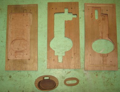
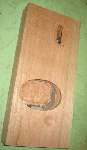
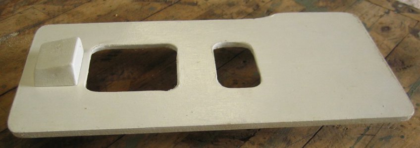
I did a sketch to work from but it was a bit of a design in progress as far as the look of the finished product. I started with a pattern made from MDF and pine; shaped for draft, painted, and also a split mold.
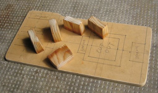
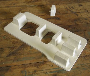
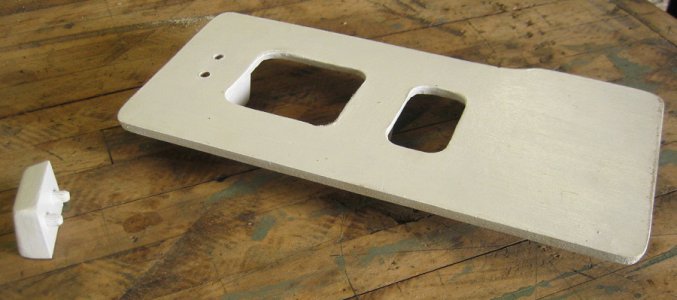
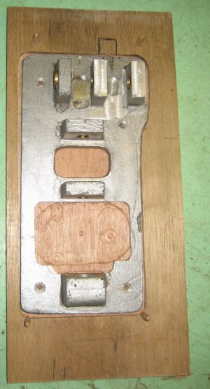
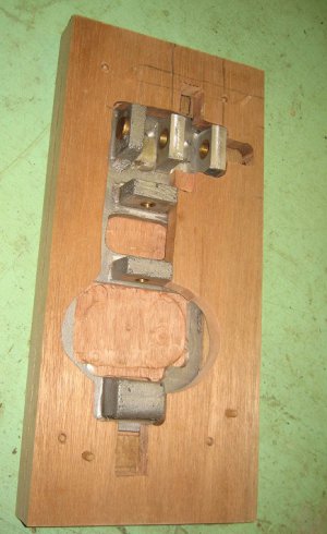
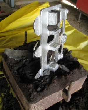
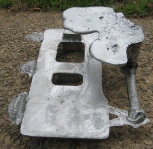
30 minutes in the furnace and what used to be a wheel rim I found on the side of the road, (I still think if the owner wonders what happened to it), was turned into something more useful, (to me).
Cheers Phil
- - - Updated - - -
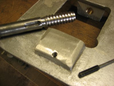
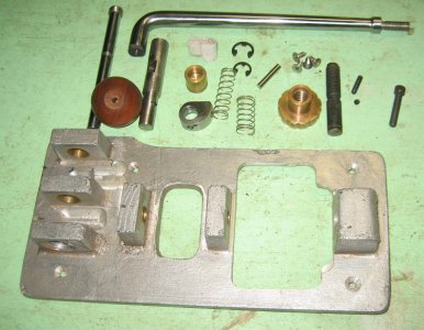
Drilled out on the mill to accept some brass bushes I had turned up on the lathe, and the “camshaft” from 4140.
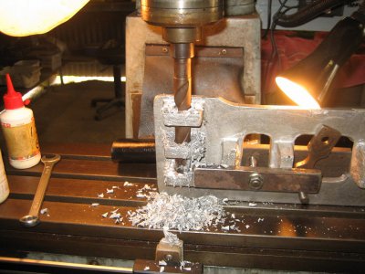
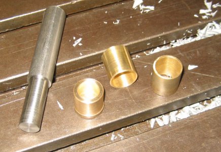
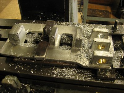
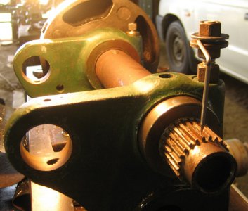
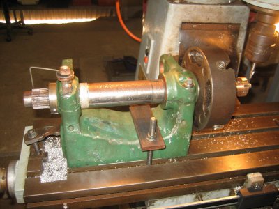
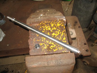
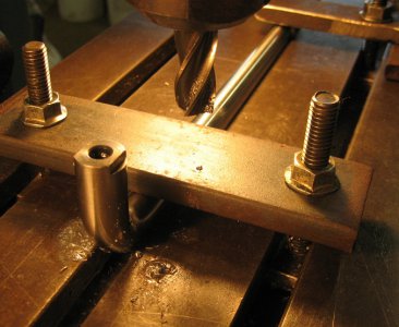
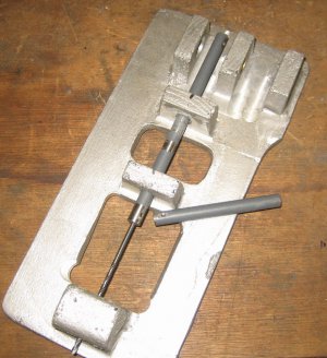
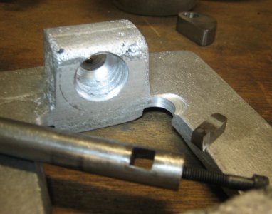
The hole for the “pushrod” was too long for even my long series drill so I made an extension from an old printer roller shaft. I drilled a pilot hole, then went up in size to the diameter of the extension shaft to keep it centered for the next bearing block. Drill and repeat, but then I had to make an even longer extension shaft to reach the back bearing block.
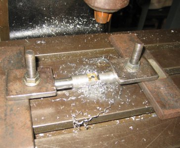
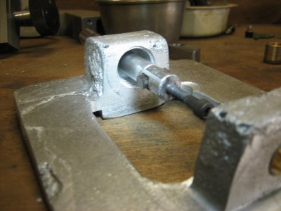
The back bearing block needed a counterbore to suit the thumbwheel I had planned. So that was another tool to make. As accuracy was not critical here it ended up being simplest to make a boring tool of sorts with a ¼” HSS cutter, I assembled the bits and just using a hand drill to power it I pulled back on the tool until it had cut deep enough.
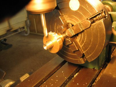
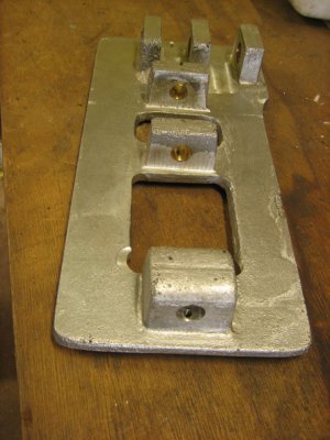
And some more brass bushes were machined up to suit the pushrod bearings.
Cheers Phil


Here in Queensland, our native nuts, Macadamias, are fairly prolific, but extremely hard. Pliers, hammers, crab crackers, are used with varying degrees of success. Pulverised nuts, pinched fingers, flying shells are often the result.
So I decided to do something worthwhile, but keeping to simple machining, and a work around of not having a rotary table or indexing head. And try to make it look nice for her.
I did a sketch to work from but it was a bit of a design in progress as far as the look of the finished product. I started with a pattern made from MDF and pine; shaped for draft, painted, and also a split mold.


30 minutes in the furnace and what used to be a wheel rim I found on the side of the road, (I still think if the owner wonders what happened to it), was turned into something more useful, (to me).


Cheers Phil
- - - Updated - - -
Drilled out on the mill to accept some brass bushes I had turned up on the lathe, and the “camshaft” from 4140.


The hole for the “pushrod” was too long for even my long series drill so I made an extension from an old printer roller shaft. I drilled a pilot hole, then went up in size to the diameter of the extension shaft to keep it centered for the next bearing block. Drill and repeat, but then I had to make an even longer extension shaft to reach the back bearing block.

The back bearing block needed a counterbore to suit the thumbwheel I had planned. So that was another tool to make. As accuracy was not critical here it ended up being simplest to make a boring tool of sorts with a ¼” HSS cutter, I assembled the bits and just using a hand drill to power it I pulled back on the tool until it had cut deep enough.


And some more brass bushes were machined up to suit the pushrod bearings.

Cheers Phil


