Open Twin 28

Ischgl99

H-M Supporter - Gold Member
H-M Supporter Gold Member
Joined
Nov 21, 2020
Messages
1,433
I started working on this Elmer Verburg Open Column Twin steam engine and took the drawings and converted them to metric as well as upsizing it by about 2x. The piston diameter is 28mm scaled up from 3/4" (19mm). I didn't want to try building something as small as the original, but with the cost of materials today, I probably should have! I can't find the original link were I found the drawings for it, but here is a link to someone that created metric drawings for it and even bigger than I did. He also rounded a lot of corners that were not in the original, as well as making some other modifications such as adding bearings for the crankshaft that wasn't in the original. http://www.modelesavapeur.com/telechargement7/elmer-44.pdf

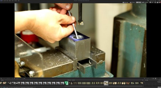
I modeled this in Fusion360 and created my drawings for it with tolerances since the original was a bit vague on what to use. The first picture is the model from Fusion. Open Column Twin - 28 v24.png
I started with the base of the model making the two rails. These have a mounting hold on each end in the step, and are threaded in three places for the columns. Once I had the rails to size, I cut the steps on each end.
IMG_0149_FB.jpgIMG_0159_FB.jpgIMG_0165_FB.jpg

Next the holes are drilled and the threaded holes for the columns made.

IMG_0174_FB.jpg IMG_0175_FB.jpg


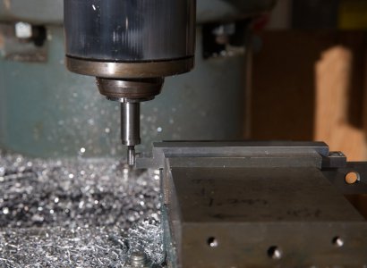
Mounted above the rails is the frame. I started with a piece machined to the proper size and then plunged an end mill to cut out the center. After the center plug was removed, the inside was cleaned up to the proper dimensions.

IMG_0180_FB.jpgIMG_0182_FB.jpgIMG_0188_FB.jpg

The next step is to add the through holes where the columns thread into the base rails and add countersunk holes for the bearing blocks. Sorry for the crappy picture, I'm working on getting better lighting for the camera.

IMG_0189_FB.jpg

Next post will be making the 6 columns.
 

Attachments

  • IMG_0170_FB.jpg
    IMG_0170_FB.jpg
    305.5 KB · Views: 6
  • IMG_0151_FB.jpg
    IMG_0151_FB.jpg
    268.2 KB · Views: 7
The columns are made from 3/8" 303 stainless rod cut slightly longer than needed. Since I had 6 to do, I used my multi-finger carriage stop. It definitely saved a lot of time doing these pieces. Each piece was put into the 5c collet chuck, faced, and then the first end turned to the right diameter for the threads. IMG_0276_FB.jpgIMG_0277_FB.jpgIMG_0278_FB.jpg

Once at the right diameter, the threads were cut using the die holder I made based off of David Best's design. You might notice this holder has a hex die in it. I already had several sizes of hex dies, so I made a hex holder from a socket to be used in the threading tool. It works better than I thought it would.

IMG_0279_FB.jpgIMG_0280_FB.jpg

Here is the first size done.

IMG_0281_FB.jpg

The columns were then threaded on the other end using the same procedure as above, except this side is longer to fit through the base frame. The photo below shows the finished columns. The carriage stop was able to hold the length to less then 0.02mm (0.001"), no complaints from me! I don't have a picture, but I made a work stop for the collet chuck using a 3/8" rod with a hole in the center for the first threaded end to fit into so that the stop was against the shoulder.

IMG_0282_FB.jpg

The next part of the cylinder base plate.
 
The cylinder base plate is made from a piece of aluminum 74x104x5mm. The first step was to lay out the holes that needed to be drilled in it. There are holes for the columns made in the previous step, to mount the cylinder that is coming up, and the large holes are for the connecting rod to pass through.

IMG_0067_FB.jpgIMG_0068_FB.jpgIMG_0069_FB.jpg

The large holes were drilled as large as I could with the drills I have, and then finished to a diameter of 31mm with the boring head. The smaller holes were then drilled. I needed to place the parallels closer to the center since I would have drilled into them for the outer most holes.

IMG_0084_FB.jpgIMG_0124_FB.jpg

Here are all the holes finished.

IMG_0131_FB.jpg

The next step is to mill a groove between the outer array of holes. The plate was placed in the vise and then the groove roughed and then finished machined to the correct size. I wrote the dimensions I needed to mill on my vice so they were handy when moving the dials. These measurements are in inches since my dials are in inches and I don't have a DRO scale on that access yet. The scale I had was broken and I haven't gotten around to replacing it yet.

IMG_0223_FB.jpgIMG_0224_FB.jpg

This is the grooves finished.

IMG_0226_FB.jpg

I could have left the plate like this, but the drawing shows the protruding arms rounded, so I decided to figure out how to best do that for each one. I first thought about filing them, but I wasn't doing a good job of making a smooth circular feature, so I made a file guide that screwed into each hole.

IMG_1088_FB.jpgIMG_1090_FB.jpg

That was very slow, so I decided to try something else. I made a table with a pin the size of the hole that I could rotate the part into an end mill. This has the other advantage of creating the rounded corner between the arms. This was probably not the safest way of doing it, but it went very well and did not at any time give me an indication it would catch and cause problems.

IMG_1091_FB.jpgIMG_1092_FB.jpg

Here is the finished cylinder base plate.

IMG_8154_FB.JPG
 
Last edited:
The next piece was actually the first one I machined, so I don't have as many pictures of it in process as I thought I had. I used a piece of a steel shaft I got form a junk yard many years ago. I don't know what material it is, but it machines fairly nicely. Steel might not be the best material to use, but hey it was basically free.

I had to hold the steel blank crosswise in my vise since it was slightly too tall to hold it properly along the length. Here in the first two pictures, I machined across the keyseat to give me a flat surface to then hold it lengthwise in the vise and to finish squaring it up.

Open 28 - Cylinder Roughing.jpgOpen 28 - Cylinder Roughing 2.jpg

After it was square, I started to drill the holes for the cylinders. The bore is 28mm and I stepped up from small drills to a 1" drill that surprisingly worked on my Burke Millrite. I thought that would be too big, but by going slow, and making sure it was sharp, I was able to minimize multiple passes I needed to open up with the boring head.

IMG_6823_FB.jpgIMG_6835_FB.jpg

Using the telescoping gages, I brought the bore diameter to 28mm and will hone it at a later time to the final dimension of 28.03-28.04mm.

IMG_6842_FB.jpg

I didn't get pictures of drilling the holes in the cylinder block, so these are after the fact. The first picture is the bottom of the cylinder block and has 6 holes where the block mounts to the table machined in the previous step.

IMG_8171_FB.JPG

The top side has several different hole diameters. The four holes in the corners are to mount the top slide plate coming in the next step and the four holes in a pattern around the center is for mounting the steam chest. The two holes in the center are the inlet and outlet for the steam. Not shown yet are the holes on the sides for the inlet and outlet fittings. I haven't decided yet on what fittings I will be using and have made a prototype to try, but will leave those unfinished until I figure out what I want to do. I also need to cut a recess in the top of the cylinder block that lets the steam into the cylinders, that will be done at a later date.

IMG_8170_FB.JPG

This last picture shows the M2 mounting holes for the slide rod housing.

IMG_8172_FB.JPG

Next up, the valve plate.
 

Attachments

  • Open 28 - Cylinder Measuring Bore.jpg
    Open 28 - Cylinder Measuring Bore.jpg
    315.8 KB · Views: 2
Back
Top