- Joined
- May 7, 2020
- Messages
- 263
Electrical diagrams don't usually survive a commercial environment. This one is pristine and I'm including it here for the 7.5hp 2-speed 1740G.

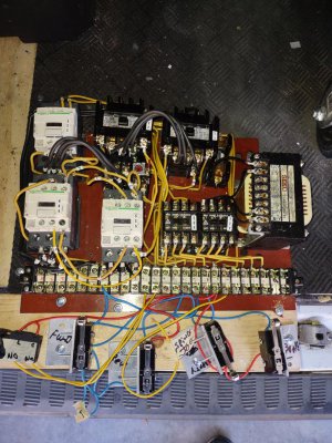
Here is a nicely preserved electrical panel per the above:

Note for those installing a Rotary Phase Converter and if your diagram looks like the above:
Wiring RPC to Lathe Input:
T1-Black -> L1-Red (R)
T2-Red -> L2- White (S)
T3-White/Blue -> L3-Black (T) Manufactured Leg
Here is a nicely preserved electrical panel per the above:
Note for those installing a Rotary Phase Converter and if your diagram looks like the above:
Wiring RPC to Lathe Input:
T1-Black -> L1-Red (R)
T2-Red -> L2- White (S)
T3-White/Blue -> L3-Black (T) Manufactured Leg
Last edited:

![IMG_20210915_121750394[1].jpg](/data/attachments/336/336253-06b01120b985c47074a8d08fa19a5bdc.jpg)
![IMG_20210915_115526767[1].jpg](/data/attachments/336/336254-effbca982e0ce066bd4df1db0c5cd6f4.jpg)