Phase Converter

shell70634

H-M Supporter - Diamond Member
H-M Lifetime Diamond Member
Joined
Mar 7, 2018
Messages
105
The mill is a Clausing Kondia
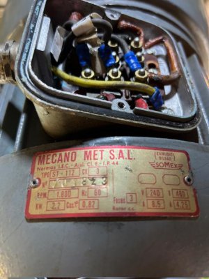
Motor data:mill motor.jpeg
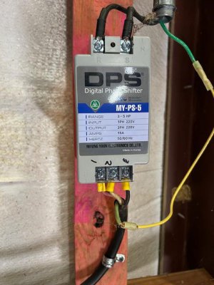
my phase converter:conv mill.jpeg

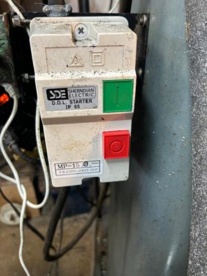
my magnetic switch:mag sw mill.jpeg

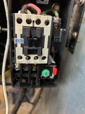
inside the switch:mag sw mill2.jpeg


Installed new belt. Motor spins freely with no binding. When I power the mill up it will run for about a minute then trip a 20 amp breaker. When connected to 30 amp breaker, the magnetic switch trips. The exterior of the motor is warm but I don't know what the temp should be. Before I changed the belt and installed the magnetic switch the mill ran fine on the 20 amp breaker.

Question one: Using a multimeter, how should I check the wiring? And what values should I be looking for?
Question two: I cannot find instructions on the magnetic switch geared to someone without knowledge (me). Is there an adjustment inside the switch I should make?

If it gets too complicated for me I will look for a qualified person for help. I do know my limitations. Sometimes
 
Put a current clip on each branch (L1, L2 and L3). Assuming you are using the 240v connection - the draw will be about 8 amps. Since you are on a static type phase converter, the current could be pretty imbalanced (so check that). If even one branch is over about 10 amps (regardless of the voltage, or if it is out of phase - doesn’t matter, current is current and if you exceed the nameplate by much, it is not good - that is why the thermal overload in the mag starter is tripping).

It sounds like one leg is up near the max for that motor.
 
are you sure the motor is setup for 2-- v, and not 480

Yup. I've been running it for 2 years on a rotary phase converter til lightning took out the control box. And it ran fine without the magnetic switch. But the switch is necessary because of our power companys habit of losing power for a few seconds at a time.
 
"It sounds like one leg is up near the max for that motor."

Can that be remedied?
 
"Don’t use the output of the converter for control purposes.
Use the input voltage"

Forgive my ignorance please. Are you saying the magnetic switch should be on the 220 single phase input side of my converter?
 
I think what he's saying is to be sure the manufactured leg goes to the motor, not to the control station. Most control stations are 120 volts so only 2 of the 3 legs will go there. The manufactured leg is only active for a short period of time. Once the motor comes up to speed the manufactured phase drops out and the motor runs on single phase. That's the reason motors powered by static converters only put out about 2/3 their rated hp.
 
Your system should be wired like this:
Wall (220v 1 phase) --> Power switch (only 2 of the 3 poles should be used) --> "Digital Phase Shifter" (2 poles in 3 poles out) --> Motor

It looks like all 3 poles of the power switch are being used which indicates to me that the system isn't wired as above? I believe this is causing the static phase converter to not operate properly. When the static converter is energized a relay is closed which powers the starting capacitor. After a set voltage is reached (or possibly a set amount of time) the relay should open and the starting capacitor is removed from the circuit... I believe this is not happening so a continually higher current is drawn until the breaker trips.

The "Digital" phase shifter is just a static phase converter with a solid state relay instead of a mechanical relay making it "Digital"... all marketing BS!

If the system IS wired as above I would highly suspect the static phase converter (Digital Phase Shifter) to be bad, not functioning properly. As above the starting capacitor is never being removed from the circuit by the relay properly opening.

As stated previously a clip on ammeter would be how I would diagnose the problem. The generated "starting" leg between the static phase converter and the motor should initially have a high current running through it until the motor comes up to speed then the current (amps) should drop dramatically when the fore mentioned relay opens removing the starting capacitor from the system.

How big is your motor? It should be between 3hp and 5hp for that static phase converter. If it is smaller than 3hp, i.e. a 2hp motor, the starting capacitor in the static converter is too big for the motor.

P.S. Please make sure the contacts on the "Digital Phase Shifter" are properly covered / insulated when you are finished to prevent future electrical "accidents".
 
Last edited:
We need to see a block diagram of your hookup, but I tend to agree with MikeinOr
Possibly the current limit setting (green knob) on the magnetic switch/overload relay is set too low
Set it at maximum and if it stays running then try lower settings until it starts tripping again, then go back one step higher
 
Last edited:
Back
Top