Phase Ii Qctp Vs. Compound Rest On Atlas 10"

Anthony G

Registered
Registered
Joined
Jul 2, 2015
Finally got around to finishing up the t-nut for my compound for the Phase II QCTP I recently purchased. But, that's not what this thread is about.

I installed and tightened the center bolt for the QCTP and slid the t-nut/bolt assembly into the compound slot. I then took the QCTP itself and slid it down over the assembly. I then found out that the body of the QCTP interferes with the upper radius of the compound casting. Here is a picture, although I'm sure that others who have installed a QCTP have had the same problem. I know the pictures isn't great, but I couldn't get the flash to properly illuminate under the QCTP where it's hitting the compound. But, you get the idea.


My question is: How did anyone else who has encountered this problem remedy it? Did you grind (YIKES!) off some of the compound rest? Or. did you make a plate to elevate the QCTP slightly above the radius of the compound casting? Or, is there another fix I'm not realizing? Just curious. Thanks
 
I figured that's what a lot of people have done. That would be difficult for me since I don't have a mill, and if I take the compound off for machining, I have no way to rig up something in the lathe and mill it with a cutter in the spindle. I suppose I could, possibly, remove the compound and do some VERY light milling in my drill press so I don't destroy the bearings. Or, just make a riser plate like I said to raise up the tool post.

This also begs the question: How do you remove the compound? I've never taken one off.
 
I did not have a mill at the time either. I was helped by a form member Dave to get the part machined. I pulled the screws at the hand wheel side of the compound and loosened the gib screws and I was able to remove my compound.

Maybe a forum member near you would be able to help you out as well. I would but MN is a ways from OH.

The riser might work but you have to consider center height.
 
That would be difficult for me since I don't have a mill

Just use an angle grinder and remove enough of the radius so that the QCTP sits level and has enough room for the corners when you rotate it. Personally, I go for "function over appearance", but if you want it pretty then file or sand the grinder marks smooth. Easy-peasy! I also used a 4" angle grinder to cut my T-nut, and it came out perfect. Obviously, I would have used a mill if I had one. Hopefully soon. Good luck, JR49
 
I did not have a mill at the time either. I was helped by a form member Dave to get the part machined. I pulled the screws at the hand wheel side of the compound and loosened the gib screws and I was able to remove my compound.

Maybe a forum member near you would be able to help you out as well. I would but MN is a ways from OH.

The riser might work but you have to consider center height.

I'm going to try and take it off. I don't think center height is really a concern as with my AXA tool post there is a lot of adjustment up and down. I think the step from the flat of the compound to the radius of the casting is only about 1/8", maybe just a little more. I don't think that would pose to drastic a change in the position of the QCTP for center position. I still may make the riser and see how it works. I can make it so it fits against the step tightly and won't rotate. If it doesn't work out, I'm only out a little time and can move on to plan B.

Just use an angle grinder and remove enough of the radius so that the QCTP sits level and has enough room for the corners when you rotate it. Personally, I go for "function over appearance", but if you want it pretty then file or sand the grinder marks smooth. Easy-peasy! I also used a 4" angle grinder to cut my T-nut, and it came out perfect. Obviously, I would have used a mill if I had one. Hopefully soon. Good luck, JR49

Yeah, it's doable with a grinder. I think I want to exhaust other means first, though. I milled my t-nut on the lathe. I bought a small angle plate and mounted it to the compound and then secured the un-milled t-nut to the angle plate, stuck an end mill in a large headstock drill chuck that came with the lathe and, after some calculations and indicating, milled away. I have some pictures of the jig I used I'm going to post for others who may want to do theirs that way. It was pretty easy and inexpensive really. Came out nice. Hopefully soon on the mill for me, too. I'm still KICKING MYSELF for not buying the nice, small Index mill that the guy had, also, from whom I purchased the lathe. I don't know what I was thinking. I wasn't thinking that day. He wanted $800 for it and I should have jumped on it. It was a nice small, garage-type knee mill. Nice American iron.
 
You are welcome to use my mill but you will have to drive to Bowling Green. Send me a PM.
 
I had a spare compound so turned mine mounted it on the three jaw chuck with the jaws in the mounting hole in the base. Do you have access to another lathe or some way to rig up a temporary tool holder?
 
You could try putting spacers underneath the block. At least it will get you back to work until someone can help you.
 
Well, I ended up biting the bullet and milling it in my drill press. This will be the one and only time that I abuse my drill press in this manner. I have an XY table for the press and I took very small cuts of about .002 each pass across the compound with a lot of cutting oil. It took quite awhile doing it this way since I took such a small cut each pass and only had a 1/2" end mill to do the work. Actually, it turned out very nice. I indicating everything in to ".000". It didn't sound like a lot of undue strain on the machine, but like I said I won't be doing it again.

Fitter Bill.........that's a really great offer and I truly appreciate it. If I would have seen your post before I did the job, I think I would have taken you up on it.

Dranreb................I thought about trying to mount it up in a chuck, but was a little apprehensive about securing it properly and locating it the necessary position to make such a cut. I guess it could have been done if I would have put a little more effort in it.

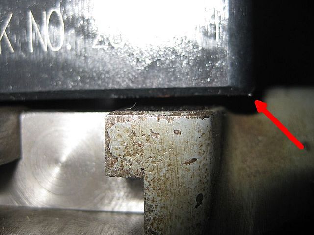
On a related note, mostly for any future members with "new to them" lathes, who also want to mount a QCTP on their Atlas 10", what I would say is DON'T MILL YOUR COMPOUND DOWN so you can swing your QCTP properly. I say this because of the thickness of the casting. Although I DIDN'T break through, my measurements afterwards of how much casting thickness is left after doing the milling is very minimal. Yes, there is still casting on the sides of the compound that has the original structural integrity. We'll have to see how long it holds up and whether the compound ends up breaking or not from repeated stress of machining. I machined the radius down to slightly below the level of the flat on the compound, but only by a few thousandths.

If I were going to do it again, I would have just followed my original instinct and made up a "riser" to raise the bottom of the QCTP up above the radius of the compound. Bill C. had the same idea. Theoretically, it would only have to be a couple thousandths thicker than the difference in height between the flat of the compound slot area to the radius of the compound casting, which is about .125 in. I think that would have been the better way to do it. A functional riser made to fit the shape of the flat surface could easily be fabricated and would not rotate when spinning the QCTP. I guess my hindsight is 20/20. If the compound ever does break and I have to get another, I will definitely be making a riser about 5/32" thick to stick under the tool post. Just my two cents.

I will say one thing positive, though. Taking the compound off allowed me to clean up all the gunk underneath it and repair the gib adjusting screws that were frozen in the lock nuts.

Thanks for everyone's advice. Moving on to mounting an old (30+ years), adjustable, swinging-arm type lamp that I acquired from Champion Spark Plug that they were throwing away because it was arcing in the bulb socket area and only turning on intermittently. I replaced the lamp holder for a few dollars. Other than the bad lamp holder, the light looks like brand new. Made in USA, too. I've been storing it for the past 11 or 12 years or so in anticipation of getting a lathe someday and putting it to use. I REALLY want to place the mount for the lamp on the back of the carriage somewhere, but I don't see an adequate place to do so. The casting is not flat and has compound sloping angles to it. I prefer the light to travel with the carriage, so the illumination stays with the cutting area of the workpiece. I might post up a pic in a new thread and ask for some member's advice on how to mount it. If anyone has mounted a light like this on their carriage, please give me your insights. Space is really limited on the back of the carriage with the gib screws and such and, like I said, the top of the casting isn't anywhere near flat. The mount has a "ball" on it, so I am stuck using it.
 
Back
Top Bottom