Phooey, my FreeCAD broke!

WobblyHand

H-M Supporter - Diamond Member
H-M Lifetime Diamond Member
Joined
Dec 18, 2019
Messages
6,447
So I have been using FreeCAD a bit. It has been really enabling to be able to design up stuff, even if I can't make it. A few days ago, I built FreeCAD from source and used it that day. Yesterday I used it. Today, I tried to use it and it won't get to the point of the app launching. Instead I get a core dump of the app (not my computer!). Yesterday and today there were some big updates pushed out in my OS. Linux Pop!OS, which is an Ubuntu variant. It could be that the updates broke stuff, but that is out of my league to track down.

So I did another git pull and rebuilt the code. It seemed to complete with no error. But it doesn't work either. I get the initial graphics at start up, then some QT and OpenGL error messages, then a program dump. That's not encouraging.

Well, I thought, how about downloading an AppImage? They are supposed to be self contained, right? So I pulled FreeCAD_weekly-builds-32821-2023-04-13-conda-Linux-x86_64-py310.AppImage from the website and attempted to launch it. You can see where this is going - it does the same thing - core dumped. Well, this is no good. I have over a 100 designs in FreeCAD. I can't view them, or edit them, or create new ones.

I'm guessing this will eventually resolve itself, but it sure is painful now. I only found out about this today because I was going to design up a split clamp for a cable from my ELS DRO cable. Tried to use FreeCAD to design the clamp, to run into this. Quite discouraging. Today our network is acting up, it's way slower than usual, to downloading that AppImage took hours. I am attempting to download an earlier AppImage to see if it works, but that's a long shot.
 
I recently ran into a situation where FreeCad wouldn't start. Just nothing happened. Win10 so no core dump. I tried to uninstall/re-install FreeCad, no change. (This was with the latest production release, 0.20.2.) Then I did the re-install and had it delete my preference and restore the default. That did it. I had just saved some different preferences for one of the workbenches. Apparently that broke it.
 
I recently ran into a situation where FreeCad wouldn't start. Just nothing happened. Win10 so no core dump. I tried to uninstall/re-install FreeCad, no change. (This was with the latest production release, 0.20.2.) Then I did the re-install and had it delete my preference and restore the default. That did it. I had just saved some different preferences for one of the workbenches. Apparently that broke it.
There was no "core dump" in the sense of what one thinks a core dump is. I got a few start up graphics then that disappeared. In the console, I got the following.
Code:
WebEngineContext used before QtWebEngine::initialize() or OpenGL context creation failed.
QGLXContext: Failed to create dummy context
Failed to create OpenGL context for format QSurfaceFormat(version 2.0, options QFlags<QSurfaceFormat::FormatOption>(), depthBufferSize 24, redBufferSize -1, greenBufferSize -1, blueBufferSize -1, alphaBufferSize -1, stencilBufferSize 8, samples 0, swapBehavior QSurfaceFormat::DefaultSwapBehavior, swapInterval 1, colorSpace QSurfaceFormat::DefaultColorSpace, profile  QSurfaceFormat::NoProfile)

[1]+  Aborted                 (core dumped) ./FreeCAD
$
So I got back to the prompt, at least. I had built the code in it's own build directory, separate from the source. So I haven't actually installed anything, merely executed the binary I produced. I suppose I could do a make clean. Or even start over again by deleting all the directories.

But all this crap started right after a bog standard apt-get update/upgrade. I hadn't played with any preferences, or done any particularly odd things. I do know 58 OS files were updated in the past two days - including the kernel, libpam, udev, systemd, xserver and a ton of Nvidia files. Whether that is relevant or not, I don't know. I do know my files are intact, but the app itself is kerflooey.

So something is up with Qt, and or OpenGL, or maybe not...
 
Solved. Nothing to do with me.

Cause: late delivery of packages (OS files), resulting in an incomplete update. Why they do this, I don't know.

Fix: Install the Gnome runtime flatpack this morning. This update was not available yesterday... But it was needed.
I really dislike this disjointed package management. Give me apt alone (which worked fine for me, unless I did stupid stuff) or give me all flatpacks. Neither package system knows about the other, and at least yesterday, they were not quite in sync. There's not a huge advantage for me using flatpacks since the downloads are huge and I have a somewhat flakey network. Sometimes the flatpack downloads take far longer than to build a kernel.

So nothing to do with FreeCAD really, the OS was incompletely updated. Now what was I doing again? Oh yeah, designing a small coupler.
 
Well, there's more weirdness. Drawing a Crosman airgun valve and having all sorts of fun.

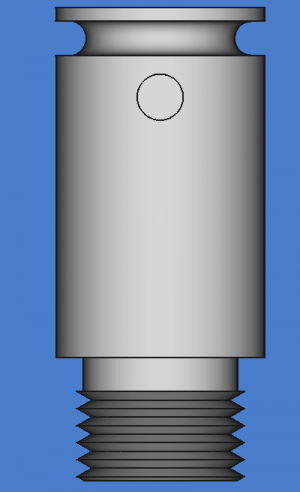
Can someone tell me what a view should look like of a body? Wouldn't the view be as if the body were NOT transparent? Well mine has some vestiges of the innards! Here's a solid view of the body.
intakebody.png
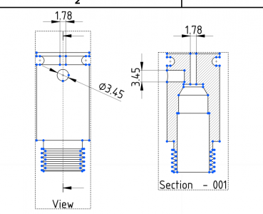
Here is the view and section
sectionviews.png
Why do I see the air inlet bore in the View on the left? (1.78mm) It shouldn't be there!

I don't get it. I'm having terrible time dimensioning things. Dimensioning some lines in a section view leads to SEG faults, which is a bit disconcerting. I'm getting disenchanted. In my perhaps pollyanna thinking, there shouldn't ever be a seg fault due to allowed operations. If I'm trying to do something the tool doesn't like, it shouldn't let me do it. I'm simply using all the features, perhaps in an inexpert manner, but isn't that how one does CAD? It could be there's some residual issue from OS updating, but this isn't a huge model, nor is it that complicated. It's just a bunch of pads, pockets, grooves and revolutions...

Just venting...
 
On the left image, the View shows a left pointing arrow, as if the observer for the section view is looking leftward. Without being anything near a draftsman, this to me looks consistent. Are you expecting the left and right 2D drawings to be in the same orientation?
 
On the left image, the View shows a left pointing arrow, as if the observer for the section view is looking leftward. Without being anything near a draftsman, this to me looks consistent. Are you expecting the left and right 2D drawings to be in the same orientation?
No, I'm not expecting that. The section looks ok.

The original view is weird, I would think that you wouldn't have x-ray vision on only part of the view. The narrow 1.78mm bore should be invisible in the "View", but there it is. It simply wouldn't be visible with a solid model. In the past, it didn't matter what the transparency was, you'd get the 2d projection of a solid version of the body. I don't understand where those 1.78mm horizontally spaced vertical lines are coming from in the view on the left.

I can attach the model, it's just me trying to recreate the disassembled air valve. Thought I could learn something by machining one. Next post, as I'm on my phone.
 
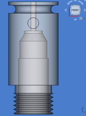
In Part Design, FRONT orientation, of the IntakeBody, with 50% transparency looks like:
1682025870568.png
The 0 transparency FRONT is as in post #5. The 3.45 mm hole is blind, it does not go through. With the physical part, you cannot see the 1.78mm bore at all, so I'd expect the same of the "View" in post #5 as well.

Full model looks like this (so far):
1682026331855.png
I haven't finished modeling the poppet seat yet. The poppet is red in this picture. Pumped air comes in on the left and goes by the check valve. Multiple pumps increase the pressure in the valve cavity. A hammer comes from the right side and pushes the poppet off the seat. This is the view you see above. The high pressure air escapes around the poppet stem, then goes through the exhaust port, into a transfer port which is connected to the barrel. Ordinarily the spring keeps the check valve closed and the poppet seated.
 

Attachments

  • airvalve.FCStd
    485 KB · Views: 0
A FreeCAD developer agreed that the little lines on the intake bore shouldn't show up on the View in TechDraw. A git commit was made to fix that 30 minutes ago. Kind of amazing really. Beats me if it fixes the SEG fault yet... Hope all I need to do is a git pull and rebuild. I'll try it out after dinner.

Edit: I lied. Just did it. Rebuild took under 4 minutes. Apparently too soon, don't think the change has propagated. Or the commit isn't to main!
 
Last edited:
Ok, I see what you're talking about. I was confusing the 3.45mm bore and the 1.78. Nice that you got a developer to respond that quickly.
 
Back
Top