Please Help mw with a Huanyang VFD

Hello All;
I found at the back of the manual a condensed version of all of the code types supported by this VFD. This condensed version covers approximately 33 pages
which is a bit much so what I have done is broke each segment into what function that segment covers. If you want details on a particular function I can the scan
that portion and post it here.
The functions and what they cover are:
P0.xxx Group Basic Functions
P1.xxx Group Start and Stop Control
P2.xxx Group Motor Parameters
P3.xxx Group Vector Control
P4.xxx Group V/F control
P5.xxx Group Input Terminals
P6.xxx Group Output Terminals
P7.xxx Group Human Machine Interface
P8.xxx Group Enhanced Functions
P9.xxx PID Control
PA.xxx Group Simple PLC
Pb.xxx Group Protection Function
PC.xxx Group Serial Command

I hope this helps so we can get this VFD running my motor.
Please note there are 127 pages in this manual and most of it is a challange to wrap ones mind around!
 
  • Like
Reactions: val
Here is my take on what's going on:
You have been talked into or duped to buy a GT series VFD, which is a vector control VFD (that means it measures what's going on with the load on the motor and compensates to maintain speed no matter what the load). That is an excellent VFD, but does not address the issue of voltage increase.
The label is pure fiction, I believe, and probably a translation mistake or two. It says that it's a 2-phase 220V input. There are 'two-phase' electricity supplies in some parts of the world, but usually 440 or 480V. The circled connections in your manual indicate however that it is suitable for single phase or three phase supply connections.
In any case, the output voltage will be whatever the input voltage is - plus or minus maybe 15% depending on the parameter settings. Maybe that's why you were able to measure more than your input voltage. Could you please tell us at what output frequency you were measuring the output voltage?
Also, this is a 5Hp VFD (4kW), so you will HAVE TO set the parameter for the maximum lathe motor current or the VFD can cook your motor!
But back to the voltage thing:
Please photograph and post the insides of your motor's terminal box - both the connections AND the inside of the cover. Usually, the connection diagram is on inside of the cover. If not, I'm almost certain I can tell you and show you how to connect it for 220V. It's generally pretty simple, even without a diagram.

The GT model may have some different parameters to the normal vectorless models that many of us have (because they are a lot cheaper), and there will be parameters related to the VFD behaviour on changing loads. So we need to be careful when we make suggestions to you as to which paramters to change!

Lastly, this VFD can auto-tune and set many parameters to the correct values itself.
The instruction you read to 'decouple' the motor to do this means you take the belt off the lathe, so the motor can run without driving anything. That way the VFD can measure the free-running (no-load) current, the no-load slip, the no-load design speed and probably the coil impedence without slip while running. It will use those values to determine a response to varying loads.

So let's go from here and set your motor to 220V DELTA mode - from 380V Y or 'Star' mode. Then you can reset the VFD to factory values (the manual will tell you how) and we'll go from there.

This VFD and motor will be able to some really fancy things - like emergency braking in a split second, normal 'spinning down', reversing under full power (think 'rigid tapping' and threading), have variable automatic limits set and things like that. Trouble is, once you have had a vector control VFD you will think of any other type as 'seriously deficient' :)

PS: I note the the seller offered to email you an ENglish manual. Did you take him up on that and got it? If not, please ask him for it to be emailed to you! It will be terrible English, but I got quite fluent in 'Chinglish' about VFD's recently (bought some used VFDs from China that had no English documentation and used on-line and Microsoft translations only....).

Cheers,
Joe
(at last count I have 9 VFDs running, 3 of them Huanyang ones, first one over 20 years ago... when they cost as much as a used car - it's still running by the way, none of my used cars from back then are...)
 
Last edited:
Good Morning All;
Yes it is a very good morning, last night I decoded to set the VFD back to factory specifications, this I did.
I then pressed the start button on the VFD and the motor started with out any problems that I have been having.
I tried this several times and in each and every case the VFD worked flawlessly.
I then connected the two drive belts to the motor which would then drive the lathe and tried the start button again, here again the motor started well in every
speed range of the lathe. I checked out the quick change transmission both in the screw cutting and power feed functions and it worked very well.

Today I want to change two parameters and that is the Acceleration and deceleration time variables. After that I want to go into the factory setting and check what they are set at however,
I expect to leave well enough alone.
This process has been a very painful one for me over that past week or so and it has made me really appreciate the value of having the support of the many good people her who have gone out of their way to try
and assist a fellow member and for that I am very grateful. Thank you all!

My next step will be in wiring up a basic On/Off switch that I can mount on the lathe to make live so much easier.
In addition I am now considering wiring up a speed controller on the lathe, I originally though about not doing this but there is a benefit to doing this versus changing the transmission on the lathe.

This will entail a new adventure for me but I am sure with your assistance this will work out fine.
I believe that I have to connect wiring from the switches to the "Control Circuit Terminals" and the change one or two functions on the VFD to support remote operations.

Thank you everyone again for helping me out it is very much appreciated.

Best Regards

Al
 
:victory::applause:
Whew! So glad to hear it's working!!! Wowza- I still wonder what setting was making it go bonkers- But the last few posts from others we're also very informative as well!


Good Morning All;
Yes it is a very good morning, last night I decoded to set the VFD back to factory specifications, this I did.
I then pressed the start button on the VFD and the motor started with out any problems that I have been having.
I tried this several times and in each and every case the VFD worked flawlessly.
I then connected the two drive belts to the motor which would then drive the lathe and tried the start button again, here again the motor started well in every
speed range of the lathe. I checked out the quick change transmission both in the screw cutting and power feed functions and it worked very well.

Today I want to change two parameters and that is the Acceleration and deceleration time variables. After that I want to go into the factory setting and check what they are set at however,
I expect to leave well enough alone.
This process has been a very painful one for me over that past week or so and it has made me really appreciate the value of having the support of the many good people her who have gone out of their way to try
and assist a fellow member and for that I am very grateful. Thank you all!

My next step will be in wiring up a basic On/Off switch that I can mount on the lathe to make live so much easier.
In addition I am now considering wiring up a speed controller on the lathe, I originally though about not doing this but there is a benefit to doing this versus changing the transmission on the lathe.

This will entail a new adventure for me but I am sure with your assistance this will work out fine.
I believe that I have to connect wiring from the switches to the "Control Circuit Terminals" and the change one or two functions on the VFD to support remote operations.

Thank you everyone again for helping me out it is very much appreciated.

Best Regards

Al
 
Happy to hear it's working.
 
Last edited by a moderator:
Hello, yes it would have been nice to know what specifications where causing the problems.
I went through the major setting this morning and recorded there values so I could compare with values I used
here are some of the values that where changed by the reset.

P0.14 Carrier Frequency Default 5.0 My choice 15
P2.01 Motor Rated Power Default 5.0 My Choice ???

In addition there was a list of motor specification that I did not know and thus guessed or left blank.
Examples are Motor Stator Resistance, Motor Rotor Resistance, Motor Leakage Inductance, Motor Mutual Inductance, etc.

I have now adjusted the ramp up and down time to three seconds and it works well.

I want to Install an On/Off switch on the lathe to control the VFD what parameters do I need to set on the VFD and what is the designation
of the terminal points on the accessories block?
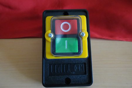
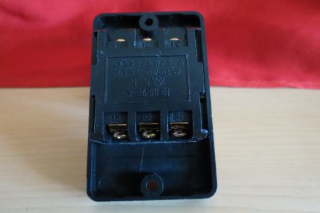
Here is an image of the Box I purchased:
IMG_1625.JPGIMG_1624.JPG

When that is complete I want to add a 10K Pot to the lathe for speed control.

Best Regards

Al

IMG_1625.JPG IMG_1624.JPG
 
I want to Install an On/Off switch on the lathe to control the VFD what parameters do I need to set on the VFD and what is the designation of the terminal points on the accessories block?
Here is an image of the Box I purchased:

P1.xxx Group Start and Stop Control

But I have no idea which parameter ot terminals without the manual
 
P1.xxx Group Start and Stop Control

But I have no idea which parameter ot terminals without the manual

Hello Jim;
Thank you for the reply.
If you would like I can scan the pages that are in the manual and then maybe we can figure this out!

Regards

Al
 
[FONT=&amp] You mentioned that the manual may be available electronically, it would be great if you could download and post in this forum. The scans are difficult to read. The ON/OFF switch is for power going to the VFD would be fine, make sure it has a sufficient rating for this VFD (probably want a 25A or 30A), you also should have some breaker or fusing (~30A). The VFD motor terminals are wired directly to the motor.[/FONT]


[FONT=&amp]Review Page 28 on in your manual. Also in the back of the manual, there usually is a tabular listing of all the commands and options (like a short form). I often print this out and make notations on that when I do my programing. I would recommend making one program change at a time, and then testing the change to make sure it is working correctly. This can be done via a USB cable on some VFDs, which greatly speeds up the process.[/FONT]


[FONT=&amp]P0.00 - On a lathe I would run Sensorless Vector control, which will give you more low end torque. Looks like a setting of 1 would be the most appropriate.[/FONT]

[FONT=&amp]P0.01 - Is for running external controls (run command source). You would want 1 for external terminals if they are connected[/FONT]

[FONT=&amp]P0.07 - Is the Frequency command source, setting to 1 specifies a speed terminal voltage source (A1) to a pot[/FONT]


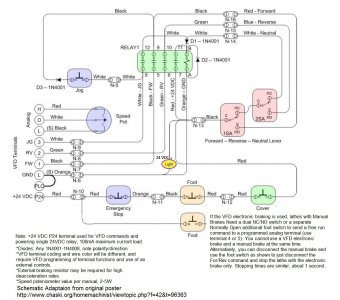
[FONT=&amp]In order to use the input and speed terminals, you need to have your controls rewired and add a speed pot. An example is attached. You pretty much gut the contactors and transformer, and use a VDC single 4 pole relay in the provided example. The voltage of the relay must be the same as the VFD control bus voltage (the total load for the bus is usually around 100-200mA). On some this is 24VDC (P24), others it is 12VDC. Another option that I commonly use is to use a small PWM universal power supply, something like a Mean Well (NES 15-24) 24VDC 15W, a main power relay and a for/rev relay. I can post an example if interested. You always want to make sure that you have an E-Stop that kills all commands and that with a power glitch, that the machine will not resume operation until a power reset.[/FONT] There is also an E-stop command that can be programmed to a terminal, but in this model I believe shuts down the VFD output to the motor, so there is no braking action on deceleration.

VFD Wiring Schematic Example.jpg

VFD Wiring Schematic Example.jpg
 
+1 what mksj said. A downloadable manual would be great.
 
Back
Top