I decided to install a MagXact to a regular PM-1236 (Not the PM-1236T). Even though it is not listed for the PM-1236, there are a few reasons I went this route.
1. It was in stock (the glass scales version that is a regular PM-1236 option is on back-order at the moment.)
2. I prefer the DRO display with rubber buttons and die cast case. Also the magnetic scales are pretty easy to cut to change the length for a custom fit.
3. It was only C-note more expensive than the glass scales version.
I have all the scales mounted and they work perfect in my quick tests vs a tenths indicator. I may make a thread with some tips if there is interest, took some time but not really difficult.
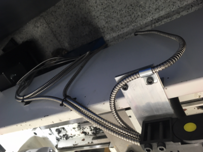
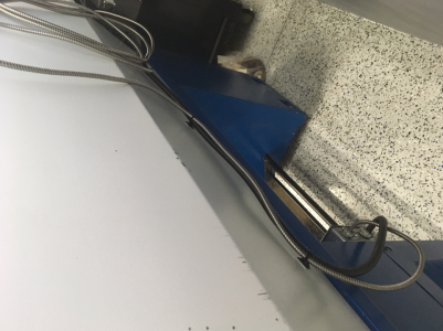
The current plan is to attach the display to the side of electrical housing with the display hovering over the head stock. The real question I have is routing the read head cables back to the display. It appears that the obvious way is through a gap in the chip shield at the head stock end, fairly close where the motor is. I am not finding many pictures to show the cable routing, I did see some that show plastic chain cable channel, but that was a pretty big lathe. There are some pictures of cables going over the chip shield, that seems like "ok" solution but not very attractive. Also some pics of the display mounted to the carriage directly, which seems to make more sense in a really long lathe and would relieve any issues with cable management, it seems weird to me though. Anyway, open to ideas here.
Attached a pic of the cross slide scale and read head, the fit is very nice. Note that the carriage is drilled and tapped for a stop bolt for the tail stock using a nyloc for the jam nut. The last thing I want is the tail stock smashing the new DRO!

1. It was in stock (the glass scales version that is a regular PM-1236 option is on back-order at the moment.)
2. I prefer the DRO display with rubber buttons and die cast case. Also the magnetic scales are pretty easy to cut to change the length for a custom fit.
3. It was only C-note more expensive than the glass scales version.
I have all the scales mounted and they work perfect in my quick tests vs a tenths indicator. I may make a thread with some tips if there is interest, took some time but not really difficult.
The current plan is to attach the display to the side of electrical housing with the display hovering over the head stock. The real question I have is routing the read head cables back to the display. It appears that the obvious way is through a gap in the chip shield at the head stock end, fairly close where the motor is. I am not finding many pictures to show the cable routing, I did see some that show plastic chain cable channel, but that was a pretty big lathe. There are some pictures of cables going over the chip shield, that seems like "ok" solution but not very attractive. Also some pics of the display mounted to the carriage directly, which seems to make more sense in a really long lathe and would relieve any issues with cable management, it seems weird to me though. Anyway, open to ideas here.
Attached a pic of the cross slide scale and read head, the fit is very nice. Note that the carriage is drilled and tapped for a stop bolt for the tail stock using a nyloc for the jam nut. The last thing I want is the tail stock smashing the new DRO!