PM-1236 motor issue

In my experience the vast majority of small single phase induction motors are designed for 50/60 operation even if they aren't labeled that way. It's cheaper than producing two motors of very slightly different design.
 
Again, just my $0.02...

If you decide to go the $$$ route (that is, get a 3 PH motor and Hitachi VFD)... I would go ahead and spring for the Leeson motor.

The subtle details of better quality things working properly, to me, are worth the extra $$$.

Be interesting to hear what Matt learns from the 'temp test'.
 
Indeed IF I go with the VFD I'll get the better motor.

I usually prefer the "buy once, buy good" strategy, whenever I can.
 
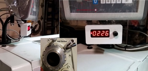
The VFD route gives very smooth and stable lathe RPM at various speed setting, you get soft start and with the added advantage of using it for braking (You cannot use the manual foot brake and VFD brake at the same time, so a foot operated brake switch would need to put the VFD into free run stop). With a braking resistor (an inexpensive 50ohm 500W off of eBay), my lathe stops within ~1 second up to 1200RPM. I just installed a MacTach meter (see below) and get almost no deviation in RPM with the VFD (with the proper program settings).

The Leeson and Marathon Metric series 3 phase motors are reasonably inexpensive in the US, probably would use something along the lines of the Leeson 1992205.00 or Marathon R319A (2HP). You need to verify the motor frame type. With a VFD you are running variable frequency, the base frequency for the motor would be 60Hz, 230V. The usable frequency range for this motor would probably be 10-90Hz, so probably around 250-2500 RPM. My understanding from what Marathon motors literature has indicated that the maximum RPM is ~2X the base of 1800, but I wouldn't want to push them that high. You might see if this vendor ships to France?

http://www.electricmotorwholesale.com/LEESON-192071.html
http://www.electricmotorwholesale.com/MARATHON-R319A.html

You might be able to work something out with Matt and get a Hitachi WJ200 VFD, either the -015S or -022S model. I have spent quite a few hours tweaking the program parameters for the WJ200-15S on my 2Hp lathe and would be happy to share the settings, or send the VFD motor settings in a file. Of course there is some individual tuning for the specific motor used and controls. It is very important that you are comfortable with the installation, as wrong wiring could be very dangerous. There is a lot of information on the web about lathe/mill VFD installations, this is a nice installation review for a Grizzly Lathe http://www.projectsinmetal.com/wp-c.../Install-VFD-on-Grizzly-G0602-10x22-Lathe.pdf .

There is also this posting for installing a VFD on a PM1236 with PDF instructions for the WJ200. Very nice, although there is no reason to cut a hole in the door for the VFD. Mine is also mounted in the cabinet, the door closes completely over the VFD. Under normal use, you do not need direct access to the VFD or it's display.
http://www.chaski.org/homemachinist/viewtopic.php?f=42&t=96363
PDF Instructions:
http://www.chaski.org/homemachinist/download/file.php?id=36080&sid=e411b7d0d43ddd6cf089ce6cc6baed6c

Mactach RPM Display and Hall Sensor.jpg
 
Last edited:
mksj,

I've got a Hitachi WJ200-022SF VFD for my mill with 3 HP motor. It is not operational yet, but I would appreciate if you can share the VFD settings with me. I realize my motor is different, but programming should be similar. Hitachi manual is not very user friendly and I would welcome any help I can get.

My PM935TS (belt/pulley drive, 3HP, 3PH) with VFD just arrived today... have not unpacked it beyond removing the plastic and getting it inside the basement (had to remove the door and put it back in); will start a new thread on it.

In a few weeks, I probably will contact you if you are willing to share the fruits of your understanding of the Hitachi VFD.

THX

GA
 
Here is an interesting bit of info:

If a single phase motor is moved to a new frequency domain the operation of any rotational switch must be checked. A 60Hz motor in a 50Hz application turning 20% slower may not achieve a speed sufficient to open the centrifugal switch. This would likely result in an immediate burn out.

Acknowledging that the reduction in operating parameters for a 60Hz motor operating at 50Hz is significant, it is NOT "dramatic" for this application. If this motor were operating at full load, 100% duty cycle in a pump or blower application it would be far more pressing. In an intermittent machine application like this I would be reluctant to attribute much, if any, of the problem on design operating frequency.
As far as the centrifugal switch is concerned, these switches are intended to open as soon as the motor achieves positive rotation, maybe no more than 20% of their operating speed; this is well within the reduced speed envelope of a 60Hz motor operated at 50Hz.
Such a high operating current (19.5 Amp @ no load) is indicative of a very high magnetic current in the motor. This can be caused by a)mechanical load, b) a reversed run winding c) a shorted run capacitor, d) shorted turns in a winding or e) a bucking winding (start winding energized).

Without belaboring the various intricacies of each circumstance... a) is eliminated, b&c) would likely result in a locked rotor or trip a breaker, d) is a definite possibility although shorted turns usually result in smoke after a short time, which this hasn't. That kind of leaves e) as the remaining culprit.

To answer your question regarding where the centrifugal switch is, it's usually located in the rear bell housing of the motor. The weighted mechanism is on the motor shaft and the switch resides on a fixed position in the bell housing. They're pretty simple.

I'll be eager to find out just what is the actual problem. As much as I'd like a VFD on my machine, I think I'd spend a little time wrenching on this problem before I threw in the towel if this were in my shop. :) Best of luck to you.

Mark
 
Last edited:
The centrifugal start switch is a function of motor speed, load should have no effect on it. "After the motor has reached approximately 75 percent of synchronous speed, the main winding can develop nearly as much torque as the two windings. Thus, an electromechanical centrifugal switch mounted on the rotor can be a simple and effective speed sensitive mechanism to cut out the auxiliary winding once the motor has picked up 70 to 80 percent of synchronous speed." http://dspace.jdvu.ac.in/bitstream/123456789/19524/1/Acc. No. DC 264.pdf

Better built motors may be more tolerant of variations in frequency and voltage. Given that the individual mentioned in my posting above on the PM1236 VFD conversion went through two stock single phase motors in a short time period before Matt recommended switching it to a 3 phase unit, does not instill confidence in the quality or reliability of the motors used. A defect in the wiring or windings would cause smoke, or the motor not achieving rated speed for the 50Hz. A bad motor start capacitor, the motor would not start. The high running current draw is consistent with the usual motor start amperage "current draw may be as much as 3 times the FLA (full load amps) during startup", so agree that the most likely issue is the centrifugal switch. Take the motor apart and see what you can do with it, possibly the centrifugal switch is sticking or sticking contacts. I do not think it is reasonably to try to change the switch release characteristics or alter the motor, for an item covered under warrantee. A replacement motor may not be subject to VAT "Replacement goods exchanged for goods exported for repair", but France may be different. So you may only have to pay the cost of shipping a new single or three phase motor if you go that route.

I will post the suggested WJ200 VFD programing parameters once I get time to put it in a tabular format.
 
As far as the centrifugal switch is concerned, these switches are intended to open as soon as the motor achieves positive rotation, maybe no more than 20% of their operating speed; this is well within the reduced speed envelope of a 60Hz motor operated at 50Hz.

Baldor and Leeson both spec their motors with a centrifugal switch that opens at 75% of rated speed.

http://www.leeson.com/TechnicalInformation/sphase.html

A 60 Hz centrifugal motor built for 3450 rpm speed operated at 50 Hz will be running at (50/60)*3450 =2875 rpm.

10 Hz decrease in frequency = (10/60) = 17% decrease in speed.

So the centrifugal switch SHOULD be opening. So if the centrifugal switch is a bit off (on a Chinese motor? unthinkable), the switch could stay shut. Leaving that starting winding engaged could easily explain the extra current draw.

I personally would source a local 3 phase motor and VFD, and stop wasting time. See if Matt will refund you the cost of the replacement motor he would have supplied. You will be happier with the performance in the end as compared to whatever cheap motor came installed on the machine. This is a common upgrade to get rid of vibrations (3 phase motor is smoother) and give you finer control of spindle speed.
 
Last edited:
Thanks for the thoughts folks.

I'm waiting for Matt to perform the temp test.

I'm chewing the VFD idea. Matt proposes Hitachi WJ200-015SF for $280 + a Leeson 2HP 3 phase motor for $150 if I want that better motor instead of the replacement 1 phase motor, or standard 3 phase motor. With shipping that will set me back just a tad less than $500, that was not an expense I expected to make that soon, so it gets me thinking. Dilema dilema! It would be a nice setup though.

Thanks for offering help on the Hitachi VFD. Seems several people are insterrested too, might be the time to create a thread for that Hitachi VFD topic, there's probably much to say about all those settings.

I also need to get comfortable with the lathe wiring to modify it to VFD. I need to go through the stock wiring diagram, see if I can relate to what I see on my lathe. If I do then I should be able to modify it to VFD. Kudo on the PDF documentation, that will be a huge help if I go that route.
 
Back
Top