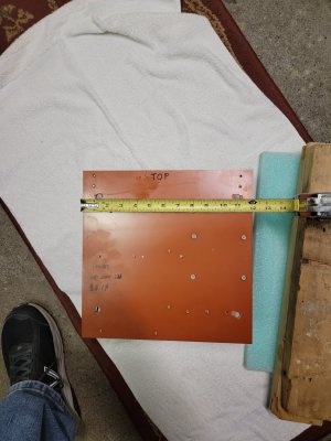
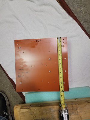
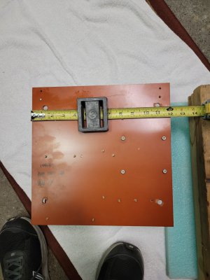
Does anyone know the dimensions of the stock control board in the PM-1440GT?
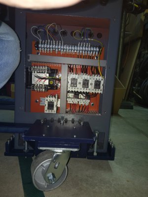
When I did my VFD conversion I simply unfastened the wires, removed the bolts holding the electronics plate and pulled it out of the lathe cavity. I then put it in a box for storage. I did look for it but did not find it this morning. (However, if any one wants to buy it I will look harder!) Nevertheless....
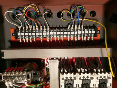
I provided even better info than this in my write up of my VFD Conversion. I made NO additional holes nor taps in the lathe stand, but used the holes already made in it. For these bolt hole locations/dimensions relative to the electronics cavity of the lathe stand see pdf page 38 of the Part 2 file called "PM 1440GT Part 2 VFDDescript links DNL L910_1440b.pdf" at the following link. While this is not the OD of the original board it shows the OD of the plate that I used and which fits in the lathe stand hole. It not only shows where the bolt holes are located, but the hole opening size and location, the plate size and location that I used, as well as the cavity openings where the wires feed in and out of the cavity. There are a couple of other wiring holes on the left and right sides of the cavity which are not shown. One on the end of the lathe (stand) is used to bring in the 220 power. You can see the plate bolting holes, feed through holes on the back and the power wires or the right in Photo 13a,
https://www.hobby-machinist.com/attachments/13a-imag2622-rear-empty-imag2622-jpg.378094/ One on the left feeds the Forward, Reverse, Neutral wires from the left end of the lathe where there is a small switch box. see
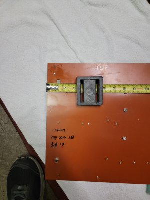
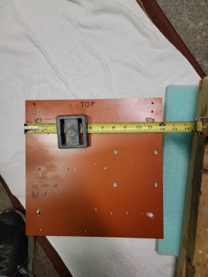
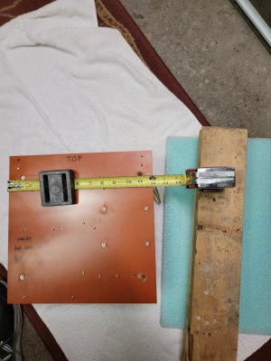
https://www.hobby-machinist.com/attachments/08a-imag3313-rear-final-imag3313-jpg.378081/ There maybe a second on the left used to feed power to the coolant pump and to the light. If you look closely at this photo you will also see the head of a screw mounted near the feed through holes (third from the right) which is a grounding screw. The original board, which you show above in red/orange is made from some polymer material which actually deforms when pressure is applied. It is ~ 1/8" thick and seems to be a bit thin/soft for the tapped bolts used to hold the relays etc. I used and aluminum plate of ~1/8" thickness, it was probably 3mm which is much stronger. Since this is a ground plane metal would be preferred anyway. It would appear that my plate would be bigger than the opening. This is the case, however the plate is inserted at an angle and is raise up to allow it to go into the entrance hole. From the drawing you will see that there is considerable space at the bottom and the plate and components can actually fit into that part if needed.
If you look at the Part 1 file, "PM 1440GT Part 1 FacOriglElecDescript DNL L910_1440 " in this same thread you will find a photo of the original plate showing the bolts. Using the bolt holes of the first drawing you estimate the over all size of the original polymer plate.
It may be in my Part 2 report, but if not I think the bolt holes were about 8mm standard metric bolt tapped. I suggest you read the description on page 9, Section D for a physical description of the cavity.
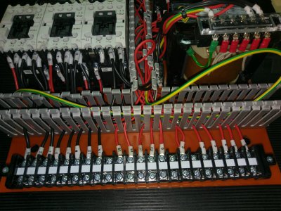
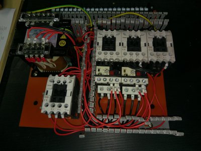
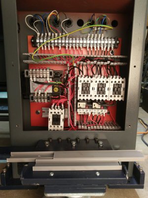
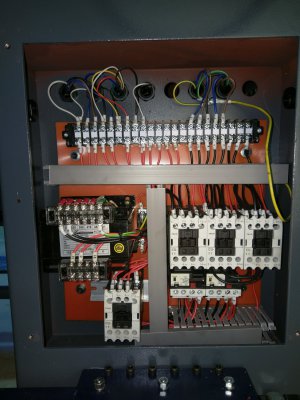
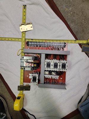
VFD conversion using solid state electronic components.
To make it easier for those who might not want to down load my Part 2 I will provide two figure pages from it here. One of these shows the info I just mentioned. The second shows the geometry of how I arranged my VFD conversion on this plate, as well as some of the dimensions.
If you really want the dimensions of the holes on the red polymer plate I can continue my search for the original plate and electronics and measure it. If you have questions about the drawings I will be happy to try to explain answer them.
In the following post I will attach some photos I took of the lathe as when it was new and with the original electronics. There were a couple of feed through holes that had not been used.
Dave L.