Pm-1440GT feed box questions.

GunPlumber

Registered
Registered
Joined
Apr 16, 2022
Messages
2
G'day Guys
I am thinking about upgrading my lathe to a PM-1440GT. Here in Australia the PM brand is sold under a different name, but it's the same machine..
I am a Gunsmith and so a large part of what i do is cut threads. Mainly imperial/UN threads but occasionally metric as well.
As part of my research into the machine I have been looking at the lead screw gear ratios of of the PM-1440 and comparing to other machines to see what threads can be cut with minimal gear changes in the back cover. To that end i decided to create a spreadsheet that would calculate the ratio of every possible lever position.
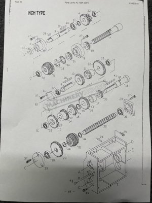
I have found the gearbox details online that shows the layout of the gearbox with the correct number of teeth on each gear set etc and was able to create the spreadsheet that calculates the final ratios for each lever position..
After I was done, I also found some one else’s spreadsheet (On this forum :)) that confirms my own so I’m confident I have it correct..
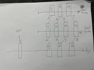
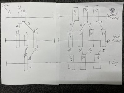
I’ve attached a few pics of the layout of the gears and I have confirmed 100% that it’s correct (the A-B C-D levers section is not shown on my sketch) However one thing has me stumped..
How can the top and bottom 30 tooth gears mesh with the center 30 tooth gear AND also the center 24 tooth gear?? IE XQ and YR.
The shaft centers are fixed and by all rights the 24 tooth center gear should be smaller dia and should not be able to mesh with the 30 tooth top and bottom gears.. Can someone explain how that works??
My first thought was some odd tooth profile that some how makes the 24 and 30 tooth center gears the same PD, but I just can’t see how that’s possible?
Has anyone ever had the covers off and have pictures of the feed box?
Thoughts??

Cheers
Lee
 

Attachments

  • Gear train2.jpg
    Gear train2.jpg
    79.9 KB · Views: 102
  • Gear train1.jpg
    Gear train1.jpg
    78.3 KB · Views: 99
Hi @GunPlumber

I have been down the same path with similar conclusions. I even made a drawing similar to yours and could never get the gears to work out mechanically. I think the gear box schematic must be incorrect. In fact the 2x portions of the gear box are also incorrect, but I managed to finally figure it out. If I recall they had the gears on the wrong shafts and in the wrong order. ( I wonder if this was done on purpose to confused competitors?) Nevertheless, I did build an Excel spread sheet which computes ALL possible TPI and Feed rates for both the 1440GT, 1340GT, and possibly may more and it also agrees with more simple spread sheets shared on HM. I put in several macros which will generate a very large table which I can then search via another macro. The table size is determined by how many external gears one has to work with and so the spread sheet is set up to allow the user to add or remove possible external gears to fit the situation. It is almost all working and I intend to share it with everyone as soon as I polish it up a bit more. Unfortunately, I got very busy a couple of months ago and did not get it finished up yet.

So I will attach the 1440GT spread sheet "engine" for you without the macros. I have removed all of the other sheets and the macros so that you do not need to fear any virus problems. I say "engine" because you select the gears via the pull down menus and this sheet provides the TIP, feeds, xfeeds, and the metric versions for you. It is backwards from what the full work book does and what is useful. I use this engine with the macros to generate the gear tables which can be searched by another macro I have written. With the gears shown there are several thousand possible combinations. You will also note that there are some pull down columns that are blank. This is for alternative lathe gear arrangements. I suggest you just leave them alone. Also there are several equations built in and you maybe wasting your time trying to figure them all out. Nevertheless, it is somewhat useful and you will get the idea of how it works if you just use the pull down menus to change the gear levers. Then look in the cells (red font) above these for the results. You will see them change. First time out I suggest you try the WXYZ pull down menu. It has been a couple of months since I looked at this, but I think I still have this sheet set up correctly. I was rewriting things when I got busy so no promises. Please, let me know if you agree or not.

Mean while I will try to make a renewed effort to get the rest of the workbook polished up for folks.

One of the issues we starting focusing on was that the lathe labels all provide low resolution or inaccurate feed rates and xfeed rates. Commonly they just say the ratio of feed to xfeed is just 1/2. And in most cases this is not true. I spend quite a while measuring mine rather than taking things apart.

You might like to look at the thread we were using to try to figure out some of the apron gearing. Several folks were contributing valuable bits to this and came up with some possible gearing systems. @Ischgl99 came up with the apron gearing which I think is the same as for the 1440GT. @Provincial also provided several valuable comments.
By "Universal" I mean any of a large number of lathes. The thread chart would include all of the change gears etc

I figured out what I did wrong with my gear calculations and come up with a cross feed ratio of 1:3.19. I measured an actual 1:3.25. I cal
Dave L., Thanks for following up on this. Since I posted, I noticed that my apron feed gear train does not have the extra countershaft (identified as F in the Jet BDB-1340A parts manual), and the lack of that gear train
 

Attachments

  • PM1440GT-TPI-FEED Single page M410_1800.xlsx
    33.9 KB · Views: 80
I think the key to this is it uses module and diametral pitch gears. Gear 14 is m2 and 30 teeth, giving it a reference diameter of 60mm. Gear 16 is 14dp and 33 teeth giving it a reference diameter of 59.7mm. So, I think one of gears of the cluster is able to drive both #14 and #16, or maybe the cluster gear is four gears and not three as it appears in the drawing.
 
Hi Guys
Thanks for the replies..

B2, thanks for sharing that spread sheet..I've only had a quick look at it while at work today but i'll have a much better look at it tonight.. It certainly looks complicated!
Just for the record i've added the A-B and C-D lever gear set to my sketch as these are actually correct in terms of over the overall ratio and also in terms of being able to mesh..

Ischlgl99
Yes i agree it must be a combination of different Module and DP gears.. I was thinking about it over the long weekend and it occured to me that 30/24 & 24/30 can be factored down to 4/5 or 5/4 so i could imagine a second set of gears (not shown in the offical drawings) with some other multiple of 4/5-5/4 with the correct shaft centers. 35-28-35 comes to mind.

I am confident that i have enough info for what i needed, but i am still very intrigued about how the gear box actually works.. When i get my hands on the new machine, once i have run in the bearings i am going to drain the oil and remove the covers and find out exactly how it works!!
I'll be sure to document it with plenty of pics and will post back to this thread..

Cheers Gentlemen!
Lee
 

Attachments

  • Gear train3.jpg
    Gear train3.jpg
    93.2 KB · Views: 86
Hi Lee,

You are right, it looks complicated, but is not really. There are a lot of extra entries which do nothing for this sheet, but which are useful for my building of other related sheets. To make one of these "Templates" or "engines" for any lathe you just need to know the gear transfer ratios for the levers and the external gear arrangements and then use this sheet as a template for the new one. The numbers below the pull down menu lists are used in these calculations via "If" conditions in the lines immediately above the pull down menus. However, this should be all set up for the PM1440GT .... so.. You can ignore all of the spread sheet entries except for the pull down menus in the center and the results shown in the red font in the rows just above (to the right and left) of these pull down cells. Most of the rest of this is either my book keeping or are used by the macros in generating the tables etc for the rest of the workbook. Just above the pull down menus are equations that effectively generate the over all gear ratios that are used to compute the red font results. If you look at the pull down menus you will see that there are 14 possible gear levers or external gears (pull down menus) which are far more than are needed for the PM1440GT, but might be needed for some other lathe model. Hence, I have tried to make the template general enough for other more complex lathe models.


The lines at the bottom are left over from my running the table generating Macro on this engine. They have no purpose here. But, these bottom lines gives you a glimpse of what a single line in the table of TPI etc will look like.


I will get the full workbook done and uploaded one of these days. I hope to work on it today.


Dave L.
 
Hi Lee, @GunPlumber

As I promised I finished off my TPI Excel workbook yesterday and finally posted it last evening.
TPI Feeds X-Feeds: Generalized Excel file for your Lathe


However, I also recalled that I had drawn up what I decided had to be the arrangement for the input factors of 2x part of the gear box that you had also tried to sketch. That is the left hand part of your above sketch.
When i get my hands on the new machine, once i have run in the bearings i am going to drain the oil and remove the covers and find out exactly how it works!!
I'll be sure to document it with plenty of pics and will post back to this thread..
So it is posted below. It differs from the manual drawing and your sketch, but works to give one the correct values. It has been a while, but I think I had found that the sketch in the manual was upside down and that one of the compound gears was just wrong. While one could get factors of 2x with other configurations, they were in the wrong order or for the knob positions or simply the wrong ratios!
As with your sketch the input from the external gears is at the top left and the bottom right shaft end feeds to the next part of the gear box. The resulting ratios are provided below the gear sketch.

I will be very interested in what you find when you open your machine up. Both for these, but especially for the more complex lever gears.

Dave L.
 

Attachments

  • Visio-PM1440GT Gear Box draft M214_1537.pdf
    43.3 KB · Views: 84
Back
Top