Narrowed down my function wants and I’m trying to keep it simple. Maybe its not as easy to wire in these controls as I think. Want to keep the controls in box on the head. Thoughts on this list? Is this doable?
Main power switch
Rev Stop Fwd switch
1 turn speed control
Momentary toggle, on-off-on for forward-reverse (mostly for tapping)
Two stage braking switch (faster braking for use with the momentary forward-reverse)
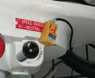
Reversing switch on back gear selector
Emergency stop (lighted when power on)
As far as VFD’s it looks like one of these three.
Hitachi WJ200-022SF currently in stock
Teco E510-203-H-U currently in stock
Automation Direct GS21-23PO. Backordered
Price point alone has me wanting to wait on the GS21-23PO.
I will also install a tach so will get a power supply as needed. I’m planning on using the machine base access door openings as mounting locations for the VFD and other parts as well as 120v outlets. (not using flood coolant). An electrical enclosure box is not out of the question yet. Is there adequate volume in the base for cooling or will it need a fan? For the controls I want, is one of these VFD’s a better option?
Mark should definitely chime in here. He da master on all this IMO.
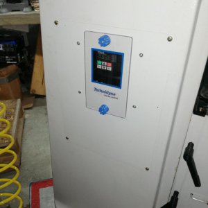
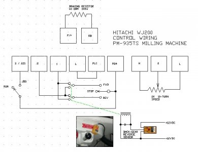
You can certainly get some of the control switches etc. into a box on the side of the head. But the relays that support the the control functions have to go somewhere, and personally, I would want those in some type of electronics enclosure. You can certainly fit the Hitachi VFD into the column, but the support electronics are another matter. Shown below is the inside of my electronics enclosure for the system Mark built that supports the functions you call out. That VFD is the Hitachi. You can see the power resister, power supplies, etc. Also, keep in mind there is cabling involved from the controls to the switch box(es) and you need some way to glad those at this end of things. This all takes real estate.

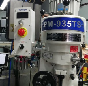
You can see what I crammed into the switch box on the side of my J-head - this is a Hoffman 150x150x120mm Stainless Steel Screw Cover Enclosure I found on eBay for $150. The inside of the box if full. This has E-stop, tach display, speed control pot, tapping switches, braking selector switch, and a switch for the spindle light.
But notice, the main on, off, forward/reverse, auto-reverse enable are in a pod mounted to the side of the knee. I would not want those controls on the side of the J-head for convenience sake, nor the would I want to up-size the box on the head any further to accommodate those switches. Although you don't plan to use flood coolant, you may discover you want some type of MQL system like a Fogbuster and controls for that as well.
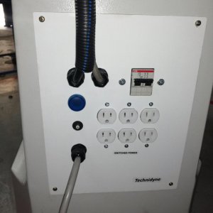
As far as the cabling goes, I recommend you put the cable plugs on the back of the boxes with the switches, not on the main enclosure box. This makes routing, tidying up the wiring, and installation a lot easier than laying on your back looking up at the bottom of the main electronics enclosure. And since there are multiple cables involved (tach sensor, back gear sensor, power, control lines, etc.) I also recommend that each cable have a different connector type so they don't accidentally get swapped. For example, here is the back of the box on my J-head (
Left to right: 3-pin connector for the tach sensor cable, 4-pin for the output to the LED light, 2-pin for the 12VDC coming into the control box):
David