PM30 Tram

Livnpaintball

Registered
Registered
Joined
Mar 8, 2017
Messages
87
So I’m almost done with my cnc conversion as I am in the process of dialing it in. Today I looked at the Tram of the Y axis and found it to be .0015 out over 6”. Is it really worth messing with or let it go?
 
I’m far from the expert around here, as I just got my first mill a little over a month ago, but since no one has chimed in yet I’ll give you my thoughts. Perhaps the more experienced folks will come along and correct me!

Unless I’m mistaken in what you are dealing with, this amount of misalignment will translate into the same amount of variance in your cuts over the same distance if the cut were made in one pass.

In other words say you had a 6” face mill (not likely going to happen, but it’s an illustration) then you would have a difference in the cut from front to rear of .0015. Now if you had a 3” face mill, then unless I’m mistaken, you would have half of that difference showing up in your cut. And if you were using a 1/2 end mill and making multiple passes to surface the same 6” wide work piece then it would be undetectable for all practical purposes. I’m basing this last statement on the math of .5” (cutter width) being 1/12th of the area measured (6”) and then dividing the variance of .0015 by 12. You end up with a variance over the .5” of the end mill of only .0000125!

So if you are making narrow cuts, your not likely going to see a problem, but put a large fly cutter or face mill on there and the variance becomes more noticeable. Noticeable enough? That’s going to depend on what you are making and the tolerances you wish to hold.

I found when tramming my mill (RF-45) that you might want to identify if the out of tram Y axis is from the column or the head to column connection. If it’s the column, that’s easy to deal with. If the column is perfectly plum and you still have an out of tram condition then you will have to go to much greater lengths to rectify the situation.

You can tram the column to account for a condition wherein the head to column is not perfectly parallel, but then you will get a forward to rearward movement of your Z axis as you move up and down the column.

Not sure if this is making sense, and I could be totally wrong on this. But this is what I’ve concluded in my own tramming ventures.
 
Last edited:
The real answer is to run some parts and measure to see if they’re within spec. I suspect the error you’re seeing will translate into unsatisfactory results but all I have to go on is my homemade CNC mill drill.

My sense is you want to start with errors in tenths to avoid stacking errors that will result in much bigger problems but ultimately it depends on the work you’re doing..

John
 
Thanks Guys, I will finish this experiment up and run a few parts and see how they turn out and go from there. At this point it is just to prove I can do it lol.
 
Knowing that these hobby mills are not as ridged as the big boy machines I would be tempted to get it as close as possible then make some test cuts. If you see what I see on my PM 727m I'm thinking you will find depending on the cutter you use the tram appears to change from what I think is flex in the machine. That in my opinion can make these smaller mills a challenge to always have perfect tram. I base this on what I see on my mill. If I run a fly cutter at a fairly large diameter I have better results going right to left ( that perfect pattern from the cutter) If I go left to right not so much, like the head is out of tram. I guess in a nutshell see how it performs and fine adjust from there.
 
Knowing that these hobby mills are not as ridged as the big boy machines I would be tempted to get it as close as possible then make some test cuts. If you see what I see on my PM 727m I'm thinking you will find depending on the cutter you use the tram appears to change from what I think is flex in the machine. That in my opinion can make these smaller mills a challenge to always have perfect tram. I base this on what I see on my mill. If I run a fly cutter at a fairly large diameter I have better results going right to left ( that perfect pattern from the cutter) If I go left to right not so much, like the head is out of tram. I guess in a nutshell see how it performs and fine adjust from there.
That’s what I’m going to do, I messed with it some yesterday trying to improve it without removing the column and it went nowhere. Thanks Tweinke
 
As luck would have it, I just checked out the tram on my 940V. It was out .0019" in Y over 6". I used a known good 6" long x 1/2" wide parallel and a -.004-0-+.004 test indicator (see attached photo). By swinging the spindle 180 degrees by hand with the gibs and the quill locked, I checked the error front to back. I wound up putting a .004" thick by 1" wide, 6" long piece of steel shim stock between the headstock and headstock support. It is horizontal, below the lower attach bolt such that the headstock is "tilted" rearward (see attached photo). That removed virtually all the misalignment. The out of tram would be most evident it you were using a fly cutter on a piece of stock. It's easy to check and I think worth it. In doing this, the X is now out of tram, but that's easy to adjust.
 

Attachments

  • IMG_0225.jpg
    IMG_0225.jpg
    697.4 KB · Views: 125
  • IMG_0226.jpg
    IMG_0226.jpg
    566.5 KB · Views: 131
  • Shimmed.jpg
    Shimmed.jpg
    618.8 KB · Views: 133
As luck would have it, I just checked out the tram on my 940V. It was out .0019" in Y over 6". I used a known good 6" long x 1/2" wide parallel and a -.004-0-+.004 test indicator (see attached photo). By swinging the spindle 180 degrees by hand with the gibs and the quill locked, I checked the error front to back. I wound up putting a .004" thick by 1" wide, 6" long piece of steel shim stock between the headstock and headstock support. It is horizontal, below the lower attach bolt such that the headstock is "tilted" rearward (see attached photo). That removed virtually all the misalignment. The out of tram would be most evident it you were using a fly cutter on a piece of stock. It's easy to check and I think worth it. In doing this, the X is now out of tram, but that's easy to adjust.
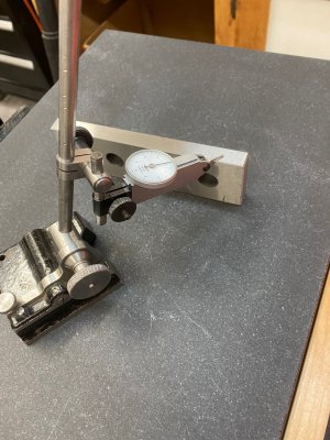
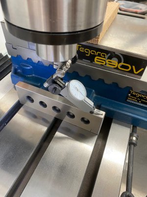
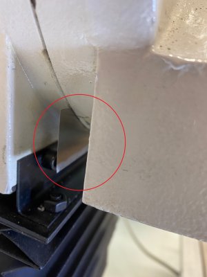
I could be wrong, but would it not be proper to tram the column first and then the head to column? Assuming of course that the column is misaligned.

Both conditions of misalignment can show in the Y axis.

I'm wondering how you ascertained that the misalignment that you saw was in the nod and not the column? I know how I would determine it, but from what you posted I don't see that you tested to see which it was before adjusting. You may have.
 
Back
Top