PM932 on the way

Congrats... I think you'll be fine on a wooden floor and leveling it as best you can only because unlevel mills makes it hard to visually line-up parts during setup. The base is very rigid and I don't think levelness impacts tram at all -but you will need to tram it. Also, I'd put about 20-40 hours on it before changing the oil. There will most likely be casting sand in there and possibly a few small burrs. The insides of the gear boxes are painted but, small amounts of casting sand does break loose after a while.

Do yourself a favor and make a base that is comfortable for your lower back and neck. That can really help a lot.

As for initial clean-up, please consider that when a new car is purchased from a dealer, they spend a good bit of time on them -filling tires with air, programming the electronics with the latest updates, adjusting the power windows for proper stopping position, topping off all the fluids, putting on pinstriping etc -ask me how I know... I've prepped no less than a hundred new cars... This is the equivalent. (BTW, when a used car is prepped for sale, many dealers usually spend 2-3x the amount of time making superficial fixes and hiding all the defects. My neighbor's son worked at a Carmax dealer and I could tell you horror stories of what they put out on the lot. He quit because of their practices -against his better sense of right/wrong).

Matt does indeed carry a supply of bearings and I believe he also knows substitute part numbers but you can avoid that issue by taking reasonable cuts. It also helps to use hogger bits instead of normal endmills when doing stock removal. They rip though material with much less effort and fewer passes. That's a win-win situation at a small cost.

When you run your power lines, measure the operating voltage and current. That's the best way of knowing the real score.

Good luck with the new machine.


Ray


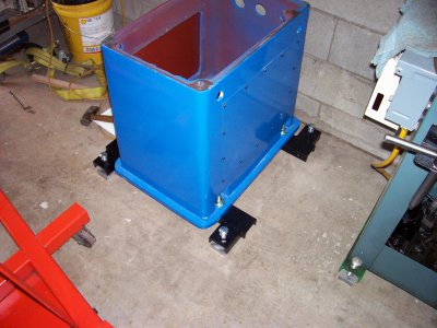
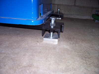
Yesterday, 09/25, my pm932 arrived in my driveway, on an extra long pallet, because I had asked Matt to not stack the base to the top of the mill crate. I`m a one man outfit, and this made it a lot easier, and safer. Lucky for me, 2 good friends came along, and helped me get the mill and base up a small ramp, and into my 12x16 wood floor outside shed. The floor is rugged, and didn`t sag. I`m thinking about bolting a couple of sheets of 3/4"x30"x30" plywood to the base for added stability- it may not pay for me to try to level it on a wooden floor-your thoughts? The milling machine , in my out door shed, will be about 60` from my house circuit breaker box, so I bought some 10-3 uf wire to hook it up. After I figure out what to put under the base, I`ll do what most of you guys did, and borrow an engine lift to hoist the mill on top of the base. Now, after it is all fastened down, I expect to have to go all over it, the way I did with my pm1127lb. Carefully clean, maybe change the oil in the gear box, attach the power feeds, tram, etc. I always thought that was part of the fun, and yes, that does require several hours to get it right. I bought a used Bridgeport, j head, years ago, that I had to spend days to get that right. Matt does, in my opinion, a very good job of checking out the machines, but after they are bounced around in crates, hoisted with chains, straps, fork trucks, etc., there is no way that they won`t need to be adjusted, especially if fine accuracy is needed. The spindle bearings on a new machine should be perfect, or darn near it, even if they are Chinese. BTW, if some one knows of replacement US spindle bearings, {numbers}, that would be welcome info for future reference. Anyone experiencing bad parts, including bearings, especially on a new machine, should contact Matt; he will make it right! Happy Milling..........Art.
 
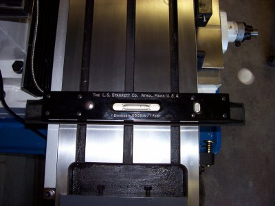
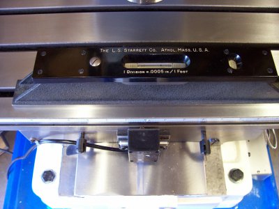
I think I would agree that the floor needs some sort of upgrade to handle this small footprint of the mill. Weight will be pretty extreme on the four small feet unless you are going to set it flat on the base. I disagrree on the need to level the machine. I don't care how much cast iron you have it will "move" over time. I have seen lathes be originally leveled and 10 days later they are off. I have heard that it may take up to 30 days for all stress to settle. Any movement you may have will translate to stress being placed on other areas (read ways) and could affect your happiness in the squareness of the part. If you are just generally playing around it may be no problem though. I leveled my 932 when I set it in place with a Starrett master level. I then waitewd 5 days before doing any work on it, other than cleaning and generally looking it over. I am still in the process of dialing everything in but will check it again in the next few day to see how much movement there has been. Based on that movement I have have to go back through it to make sure everything is still to my liking as far as the tramming is concerned.

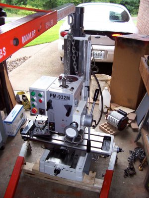
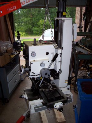
I picked my mill head up by removing the motor and using those bolt holes to attach the lift. I have seen other do it differently, but by removing the motor (4 bolts and electric lines) you are very close to centering the weight of the machine. You can then just use the y and x axis feeds on the table to level the load for a smooth even lift.


Yesterday, 09/25, my pm932 arrived in my driveway, on an extra long pallet, because I had asked Matt to not stack the base to the top of the mill crate. I`m a one man outfit, and this made it a lot easier, and safer. Lucky for me, 2 good friends came along, and helped me get the mill and base up a small ramp, and into my 12x16 wood floor outside shed. The floor is rugged, and didn`t sag. I`m thinking about bolting a couple of sheets of 3/4"x30"x30" plywood to the base for added stability- it may not pay for me to try to level it on a wooden floor-your thoughts? The milling machine , in my out door shed, will be about 60` from my house circuit breaker box, so I bought some 10-3 uf wire to hook it up. After I figure out what to put under the base, I`ll do what most of you guys did, and borrow an engine lift to hoist the mill on top of the base. Now, after it is all fastened down, I expect to have to go all over it, the way I did with my pm1127lb. Carefully clean, maybe change the oil in the gear box, attach the power feeds, tram, etc. I always thought that was part of the fun, and yes, that does require several hours to get it right. I bought a used Bridgeport, j head, years ago, that I had to spend days to get that right. Matt does, in my opinion, a very good job of checking out the machines, but after they are bounced around in crates, hoisted with chains, straps, fork trucks, etc., there is no way that they won`t need to be adjusted, especially if fine accuracy is needed. The spindle bearings on a new machine should be perfect, or darn near it, even if they are Chinese. BTW, if some one knows of replacement US spindle bearings, {numbers}, that would be welcome info for future reference. Anyone experiencing bad parts, including bearings, especially on a new machine, should contact Matt; he will make it right! Happy Milling..........Art.

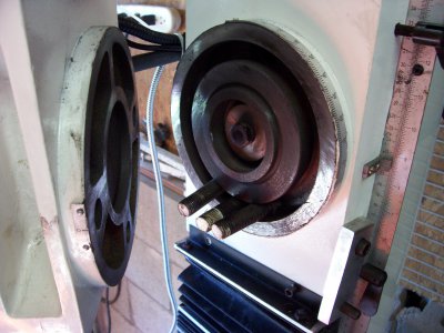
mill3.jpg mill4.jpg mill5.jpg mill6.jpg mill7.jpg mill8.jpg
 
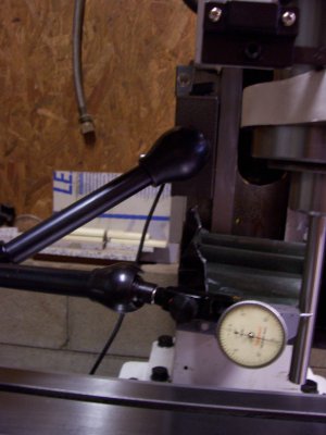
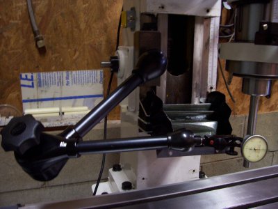
May be a little overkill, but this is how I square the mill. Maybe the pics will help also, if not give me a shout.

I attach a dial indicator (0.0005) to the mill column ways after removing the way cover. Install the best (straightest) rod into an R8 collet. Any size will work, but I use a ground 1/2 drill rod about 7 inches long. Lock the quill. I also will usuall increase the gib tension to reduce any slop that may be inherent, usually about a 1/2 turn down should be sufficient. Indicate off the side of the drill rod in the x axis direction of travel.

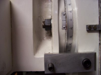
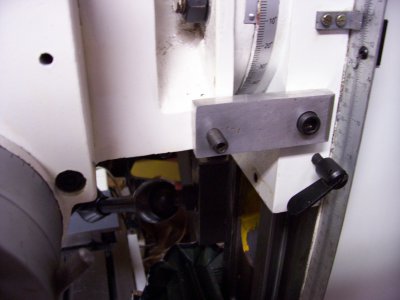
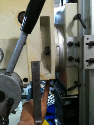
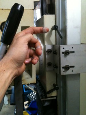
Set the mill as slow as it will run and look at the variation closest to the quill. This is where the rod does not have to be exactly true, but the better it is the easier it is to interpolate. Whatever the readings are, you are looking for the mid point of the swing. Make a note of this mid point number. Now raise the head (while mill continues to run) so that you will be indicating off the very end. The readings will probably get worse, but again you are looking for the mid point of the variations. If the difference between those two numbers is say 0.005 then you head is out about 1/2 that distance. Figure which way the head needs to be tilted and loosen the three bolts that hold the head to the column and try to rotate is best you can. Just loosening the bolts will cause the readings to change so it is a guess at best. In one of the pics I attached there is a fairly simple bracket I made that greatly assist in making slight tweets to the head. Just a 1/2 plate of aluminum tapped with a 3/8-16 socket head into the column. Other end has a 3/8-24 set screw. The back side of the plate is releaved down to 7/16 thickness to give a slight clearance of the set screw to head. Once you have this direction set (may take 3-4 attempts) you can check the rod in the y axis direction of movement using the same procedure as above. Hopefully this will be close to square. Mine head had a slight downward nod of about 0.004. You could just shim the bottom of the head on its rotation plate, but any time you move the head, you would be all messed up trying to figure where the shim should go and how much was needed.

In looking at the head attachment, there are some inherent design problems. Attachment bolts are at 3, 6, and 9 position. This means that about 50% of the head area has no support. A bolt at the 12 oclock position would be great (probably would have eliminated my head from nodding down) but it just was not incorporated into the design. I did removed the mill head from the column and did a honing of the plate on the head and the column, concentrating on removing the most material from the top most portion of the plates. I was successful in removing about 0.0015 of the nod. There is a pic showing this. I also have designed a bracket that will allow the mill head to be bolted at the 12 oclock position, but have not got around to fabbing it up yet. Now you can put it back together and measure your success in the y axix position. Don't forget that all the work you did in the x axis postion has now gone down the tube. The alignment bracket (if you decide to make one) will however allow you to get nearly perfect from the start. Look at the pic of the degree wheel on my head. Actually shows it is 1/2 a degree off. Fine job putting that bracket on.

Don't forget to loosen up your gib when finished.

I will add additional pics and description of tramming the head to the table soon. This above should take you a while anyway. It is fairly easy compared to the above. A lot of folks might just tram the head to the table and be done. In my estimation though, if you don't consider these factors in the column being off you may never realize why pieces don't come out dimension wise. Just tramming the head to the table only measures error at the one point you have the z axis set to and in my estimation is well worth the trouble. In fact I have had my 932 for 2 weeks and have still not produced a chip. Getting everything as close as possible when it is new is a lot easier than working on a dirty worn piece of equipment any day.


Just also wanted to give Matt a big thanks for having great customer service. He and Nicole run a first class operation. He has been prompt to replace parts that are not up to spec and is a great source of helpful knowledge.


Please post pictures of what you went through. I am curious how you trammed the head to the column.

edit: just wanted to add that 2-4 thou slop on the spindle when locked seems like a lot.

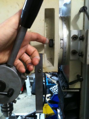
mill11.jpg mill18.jpg mill9.jpg mill12.jpg mill10.jpg
 
I haven`t set my mill up yet, as I`m still upgrading the shop, but something did come to mind about the head possibly nodding down. When I go to actually set up and adjust the mill, there is no way that I would want to alter the rotational surface of the head to compensate or adjust it for slanting or nodding down. I don`t have the skill or experience to do it right, which means that it would probably be worse than before I started. Instead, I believe that I would loosen the 4 column bolts, and slip a steel shim or two under the front bolts then tighten them back down again. I agree that it would be better to have a bolt at the 12 o clock position, to help eliminate sag, but it has been already stated, that there is no room for it. I would be interested in seeing a bracket that would help hold up the head, and still not interfere with its functions. Best........Art.
 
I shimmed the column on mine it was .008 out and got it down to less than .0005 out.
 
Thats a perfectly acceptable method and will cover all your needs. I'm a little confused about the issue of head nod as I don't think it's even remotely possible; matter of fact, any force strong enough to cause the head to nod would probably crack the column first. Here's some photos and descriptions:

There are 3 bolts that attach the head to the column. Each bolt is approximately 5/8" dia with a 1" nut. I'm pointing to one of the side bolts and there's another on the opposite side.

HN2.JPG

There's another bolt underneath at the 6:00 position which I'm pointing to. All the bolts and nuts are the same.

HN3.JPG

The circular areas that allow the swivel are 7+" in diameter and the cast iron is about 1" thick on each side (2" of cast iron). I don't bother to use a torque wrench on those bolts but, recommended torque for bolts that size is about 75 ft/lb. Since I'm not interested in getting a hernia, I just grab the appropriate box wrench, give it a good tug -and forget about it. Each bolt is capable of about 7000lbs of clamping tension so, if you want 21,000 lbs of tension holding the head on, knock yourself out. The head is going to nod? Really?

If there's any reason the head nods, it's because the gib locks were left loose:

HN1.JPG


I suppose ideally, the 3rd bolt could have been located at the 12:00 position but since every Rong-Fu and all the clones are made this way -and since I've never heard of any problems with head nod, I think the current design is doing it's job.


Ray


I haven`t set my mill up yet, as I`m still upgrading the shop, but something did come to mind about the head possibly nodding down. When I go to actually set up and adjust the mill, there is no way that I would want to alter the rotational surface of the head to compensate or adjust it for slanting or nodding down. I don`t have the skill or experience to do it right, which means that it would probably be worse than before I started. Instead, I believe that I would loosen the 4 column bolts, and slip a steel shim or two under the front bolts then tighten them back down again. I agree that it would be better to have a bolt at the 12 o clock position, to help eliminate sag, but it has been already stated, that there is no room for it. I would be interested in seeing a bracket that would help hold up the head, and still not interfere with its functions. Best........Art.

HN1.JPG HN2.JPG HN3.JPG
 
Ray,

Here is a very simple test you can conduct to see that the head does in fact naturally nod down because of inadequate clamping force.

Install a ground test rod in your head and set an indicator to read off the front face of the rod. Take a simple 24" wood working bar clamp and place it from the front of the head to the back on the column (running along side but clearing the motor). With almost no clamping force addlied to the bar clamp you will see that the indicator reading will start to change DRAMATICALLY! To me this is a definite indication that clamping forces are not adequate to counteract the moment of interia created by a 250 pound head hanging 18" out from the column.

While shimming the column base as others have mentioned can reduce this nod, it is not fixing the problem. You are basically knocking something else out of square to compensate for the nod. And as the weight of the head is not symetrical, any time the head is rotated out of this "shimmed position" it will no longer be plumb. In my estimation, fixing the nod problem at the source is the only way to consistently be assured things are staying static.

Thats a perfectly acceptable method and will cover all your needs. I'm a little confused about the issue of head nod as I don't think it's even remotely possible; matter of fact, any force strong enough to cause the head to nod would probably crack the column first. Here's some photos and descriptions:

There are 3 bolts that attach the head to the column. Each bolt is approximately 5/8" dia with a 1" nut. I'm pointing to one of the side bolts and there's another on the opposite side.

View attachment 61373

There's another bolt underneath at the 6:00 position which I'm pointing to. All the bolts and nuts are the same.

View attachment 61374

The circular areas that allow the swivel are 7+" in diameter and the cast iron is about 1" thick on each side (2" of cast iron). I don't bother to use a torque wrench on those bolts but, recommended torque for bolts that size is about 75 ft/lb. Since I'm not interested in getting a hernia, I just grab the appropriate box wrench, give it a good tug -and forget about it. Each bolt is capable of about 7000lbs of clamping tension so, if you want 21,000 lbs of tension holding the head on, knock yourself out. The head is going to nod? Really?

If there's any reason the head nods, it's because the gib locks were left loose:

View attachment 61372


I suppose ideally, the 3rd bolt could have been located at the 12:00 position but since every Rong-Fu and all the clones are made this way -and since I've never heard of any problems with head nod, I think the current design is doing it's job.


Ray
 
Hi P500hemi / all,

Allow me to explain how I tram the head.... In the +/- X direction, the head swivels so, to tram that, just loosen the swivel bolts until it's perpendicular to the table -done! Admittedly, it would be nice if there was a push/pull set screw mechanism to achieve fine control but that's not possible as it would then interfere with the ability to rotate the head to a large angle for some special purpose cut.

In the +/- Y direction, you need to loosen the column bolts and put shims in the front or back of the column. -Done! Admittedly, it's a little bit of a pain but, that's the nature of a Rong-Fu type mill.

As for deflection... Even though that column is 8" square cast iron, everything flexes with tension on it and with any TDI, you can measure it. It's largely of no consequence in this case though as I can totally guarantee that the tool, spndle, spindle locking mechanism and/or R8 tooling is flexing an order of magnitude more than the column and head is. If there is any form of head nod, it will come from the miniscule amount of play between the column dovetails and gibs.

As for the circular pivot area: When you take two round 7.5" diameter pieces of metal and bolt them together with thee 5/8" bolts those two pieces are stuck together and no humanly applied force will get them apart. If you are putting shims between the round plates... -don't do that, it's not necessary and will do more harm than good.

A personal example of deflection: In the lathe, I was making 6 rollers for a laminating press once... 3.5" diameter 1045 about 2.5 feet long. Bar stock like that weighs about 100lbs each. I had it in the chuck in one end and was setting-up the center support to drill the far end. The TDI was setup and in contact with the piece near the chuck. Once I got the center hole drilled, I removed the center rest and just the weight of the piece caused a deflection on the TDI of about 8 thou. The slightest touch at the far end with your finger tip would cause it to deflect 4-5 thou more... This is the nature of deflection of longer pieces.

In all honesty, I'm having trouble following along with your measurement setup. I'm all ears and eyes to learn something so please don't be afraid to expound on the setup -but, it does indeed sound like you're measuring the normal deflection you would expect from a long column with a force applied to it.

Finally, as mentioned before, there are probably a few hundred thousand Rong-Fu and clones out there and if this head nod were an issue, it would be a common concern, forefront in our perception and common knowledge of the machine...


Ray
 
Ray,

Here is a very simple test you can conduct to see that the head does in fact naturally nod down because of inadequate clamping force.

Install a ground test rod in your head and set an indicator to read off the front face of the rod. Take a simple 24" wood working bar clamp and place it from the front of the head to the back on the column (running along side but clearing the motor). With almost no clamping force addlied to the bar clamp you will see that the indicator reading will start to change DRAMATICALLY! To me this is a definite indication that clamping forces are not adequate to counteract the moment of interia created by a 250 pound head hanging 18" out from the column.

While shimming the column base as others have mentioned can reduce this nod, it is not fixing the problem. You are basically knocking something else out of square to compensate for the nod. And as the weight of the head is not symetrical, any time the head is rotated out of this "shimmed position" it will no longer be plumb. In my estimation, fixing the nod problem at the source is the only way to consistently be assured things are staying static.

I have a solution! Let`s get rid of all these Chinese mills, and go out and buy a bridgeport!.....Art.
 
LOL... yes, a mill weighing three times as much (for better or worse) certainly changes the landscape but since the heads on those types of mills also rotate around the Z axis, you have an extra axis to worry about.

In all honesty, I've never had to adjust tram in the Y axis on my machine -and it's 5 years old now. When I got it, I made a rotating type tram checking tool and I used it for the first few years but somewhere along the line, I think I accidentally used the piece of metal for some other project -whoopsie... Upon setup, it was within +/- 0.0002" and I was foolish enough to start adjusting it but, common sense took hold and I soon realized that vise setup and other factors are far more likely to cause problems.

About two years ago, I had an accidental hill climb with a 1" carbide bit. Bright flash when the bit blew up and the piece dislodged from the chuck. I actually checked my abdomen to make sure I didn't have a "bullet" in my guts. The replaceable soft jaws I had in the vise and the piece itself were trashed -but no damage to the machine and tram was still dead-on. I could go right now and make a 5" square block and it would be within a thou on all dimensions. With care, I could do better but, a surface grinder is the right tool to address that.

In the X direction, I've never had the swivel move off axis in the least bit. The 1" combination wrench I use is about 14" long and just putting a little love grunt on the swivel nuts is more than adequate to keep things put.

Also, some folks have mentioned a 0.008" discrepancy. In the X direction, that is totally understandable and it simply means the swivel needs adjustment. In the Y direction, I'd be very surprised to see that amount of variance assuming unless the spindle and gib keys weren't locked and tooling properly tightened. With this type of machine, the Y direction is adjusted once and you check it every now and then -and sooner or later, you'll get tired of observing the same readings.

There's an awful lot of RF-type mills out there. I've done a good bit of precision work on them along with a lot of other people. They're the next best thing to a monster mill costing twice as much, weighing three times more and taking-up three times the floorspace. If I had the space/money, I'd get one -but I'd also keep the square column.

Ray


I have a solution! Let`s get rid of all these Chinese mills, and go out and buy a bridgeport!.....Art.
 
Back
Top