- Joined
- Jun 26, 2014
- Messages
- 619
Well I have decided I need a rotary table of some sort for my mill, but at present I'm not inclined to hand over the sort of money that seems to be necessary to acquire a new one (and second hand ones seem next to impossible to find over here).
So the plan is to build something resembling a basic rotary table from the materials I have at hand (i.e. little additional cost) as an initial tool to get me going. To this end the attached is what I have come up with as a starting concept (to be refined as the build goes along).
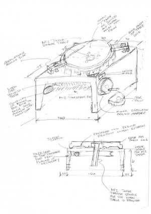
- Body will be from a piece of 140mm x 60mm channel
- Table will be 140mm diameter cut from a piece of 16mm plate
- Table will have either small 'T' slots or just a series of drilled and tapped holes for mounting clamps
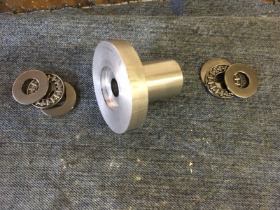
- Most of the table bottom will be recessed so it is bearing on only a couple of rings to reduce friction when turning
- Worm gear will be cut from 12mm plate and hobbed with an M12 tap in the lathe chuck
- Worm gear size is limited to around 105mm diameter to fit in the 'flat' area inside the channel so will be either 180 or 120 teeth to give a whole number of degrees per rotation of the drive handle
- Worm drive will be M12 treaded rod and probably have some fine adjustment on the position of one end to ensure if engages well with the worm gear (or possibly an idler gear to force the threaded rod into the worm gear)
- Spindle will have a MT2 taper through the centre to use accessories (such as a drill chuck) with the table detached (I don't want the taper hole to go right through the table as that could interfere with mounting small work pieces on centre
- Some sort of clamping arrangement to lock the table in position when actually milling
- One end of the channel will need to be closed with a piece of plate to allow it to be used vertically (the distance between the channel sides is just such that one will always seem to fall into a slot on the mill table if left open)
Any suggestions / recommendations / "Why the hell are you doing it that way?"s will be most appreciated as I go along. As I said this is a concept design that will probably be highly modified as things progress, but hopefully ends up with something that is usable (although I'm not expecting it to be perfect).
So far I have cut the channel, cleaned it up and marked out the plate to cut the table.
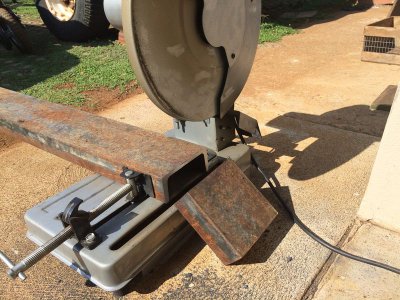
Cutting the 140 x 60 channel for the body of the cut off saw
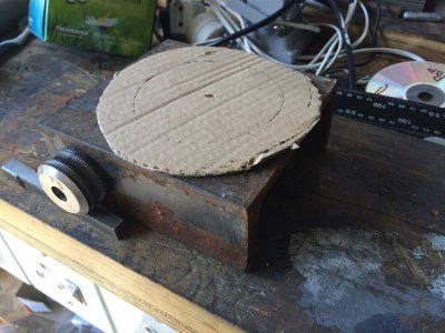
Rough mock up to visualise sizes
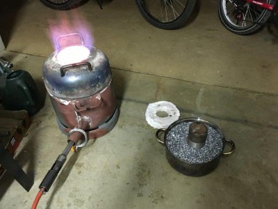
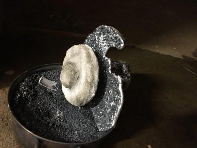
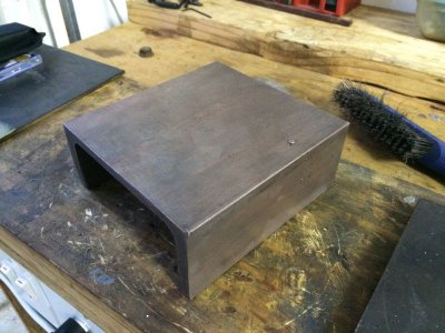
After cleaning of the body piece by electrolysis. There is some weld splatter on the channel but I will mill/face all the sides/edges once I have welded on the tabs that will become the bolting down slots and closed up one (or both) of the open faces of the channel.
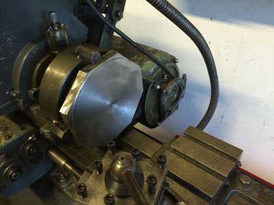
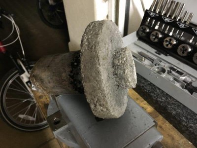
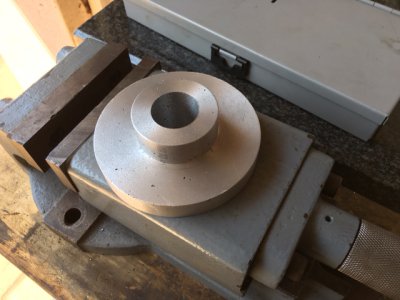
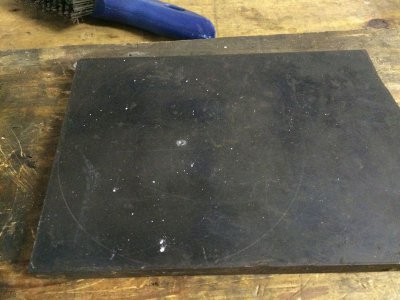
Marked out plate for table. Just happened that the largest piece of scrap I had can just fit a 140mm diameter.


So the plan is to build something resembling a basic rotary table from the materials I have at hand (i.e. little additional cost) as an initial tool to get me going. To this end the attached is what I have come up with as a starting concept (to be refined as the build goes along).

- Body will be from a piece of 140mm x 60mm channel
- Table will be 140mm diameter cut from a piece of 16mm plate
- Table will have either small 'T' slots or just a series of drilled and tapped holes for mounting clamps
- Most of the table bottom will be recessed so it is bearing on only a couple of rings to reduce friction when turning
- Worm gear will be cut from 12mm plate and hobbed with an M12 tap in the lathe chuck
- Worm gear size is limited to around 105mm diameter to fit in the 'flat' area inside the channel so will be either 180 or 120 teeth to give a whole number of degrees per rotation of the drive handle
- Worm drive will be M12 treaded rod and probably have some fine adjustment on the position of one end to ensure if engages well with the worm gear (or possibly an idler gear to force the threaded rod into the worm gear)
- Spindle will have a MT2 taper through the centre to use accessories (such as a drill chuck) with the table detached (I don't want the taper hole to go right through the table as that could interfere with mounting small work pieces on centre
- Some sort of clamping arrangement to lock the table in position when actually milling
- One end of the channel will need to be closed with a piece of plate to allow it to be used vertically (the distance between the channel sides is just such that one will always seem to fall into a slot on the mill table if left open)
Any suggestions / recommendations / "Why the hell are you doing it that way?"s will be most appreciated as I go along. As I said this is a concept design that will probably be highly modified as things progress, but hopefully ends up with something that is usable (although I'm not expecting it to be perfect).
So far I have cut the channel, cleaned it up and marked out the plate to cut the table.
Cutting the 140 x 60 channel for the body of the cut off saw

Rough mock up to visualise sizes

After cleaning of the body piece by electrolysis. There is some weld splatter on the channel but I will mill/face all the sides/edges once I have welded on the tabs that will become the bolting down slots and closed up one (or both) of the open faces of the channel.

Marked out plate for table. Just happened that the largest piece of scrap I had can just fit a 140mm diameter.


