- Joined
- Dec 23, 2019
- Messages
- 1,138
As documented here, I've been building a Quorn tool and cutter grinder. This is something of an antiquated design, originating in the 70's way before the advent of affordable commercially available collets or, indeed, precision ball bearings. As such, it relies on what was available to the author for it's spindle design: silver steel and magneto bearings with home-made arbors and collets. I have no doubt it's an adequate arrangement - after all, thousands of Quorns must have been produced to date - but it's not in my nature to leave well alone. I thought a spindle build deserved its own thread.
I decided to design a modern spindle with an ER20 taper, precision collets for which are readily and cheaply available and it allow for far more flexibility in tool and mounting choice than the simple home-made affairs suggested. The original design uses a pair of 13mm ID magneto bearings back to back and preloaded with springs. I should admit at this point that I have manufactured a spindle to plans, but found myself thinking it looked a little weedy. After much musing, and having re-watched Robin Renzetti's excellent video on spindle rebuilding/design, I decided to essentially miniaturise the Bridgeport design. At the business end this uses a pair of precision angular contact bearings, matched from factory (DB ground) to have the correct preload when placed back-to-back, supported at the other end by a standard roller bearing - in this case, dealing with the lateral load from the pulley. The original spindle case ends up around 35mm, but there's enough meat in the casting it gets held in for a 40mm case. The obvious choice, then, was a Nachi 7003 precision bearing pair, each measuring 17x35x10mm.
Having decided on the bearing arrangement, I turned my attention to how to manufacture the spindle itself. I can't even buy silver steel stock for the price that even a decent brand ER20 straight shank holder will set you back, let alone drill and bore the centre down the 200mm length! The only sticking point is that only 16mm and 20mm are available - not 17mm. I took a leap of faith that a 20mm shank wouldn't be so hard that I couldn't machine it. As far as I can tell, while it's some kind of tool steel it's not been made particularly hard and while it would eat HSS, machined really nicely with carbide. But we're getting ahead of ourselves....
After much pondering, I came up with this:
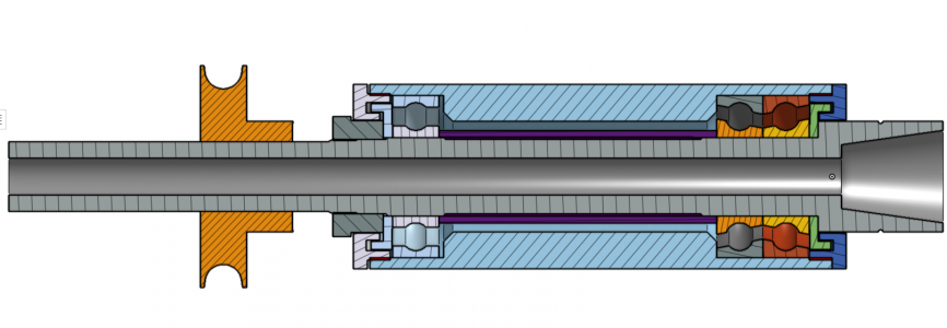
It's literally a miniature clone of the Bridgeport spindle, though I omitted the spacers they use between the bearing pair. No doubt this is for extra stiffness, but I doubted my ability to make two perfectly length matched spacers having no surface or cylindrical grinder, so opted for simply using the bearings back-to-back as the manufacturer recommends and doubt I'll regret my decision. I was too lazy to model threaded portions, so red patches mark interference fits and represent fine pitch threads.
On to construction:
Helpfully, the manufacturing process leaves a chamfer in the end of the Er20 holder. I planned to use this to steady the end and made up an arbor which fit the taper at the other end.
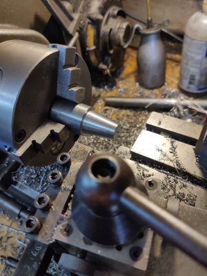
With this arrangement I could finish every operations I needed to do in one setup. Great for critical concentricity:
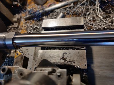
Straight off the tool. Gorgeous. Gotta love hard turning!
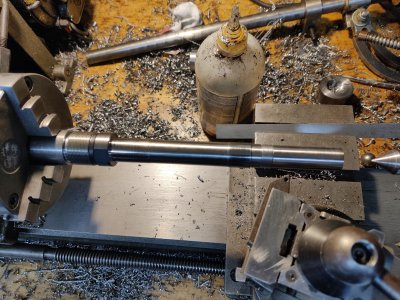
You can see the two journals slightly proud. It took some breaking free of the taper, which I'll take as a sign of a good fit. The journal for the single supporting bearing is left a heavy sliding fit, with the journal for the main pair more of a very light interference fit. This eases assembly tremendously, as does the relief between the two journals. You really, really don't want to be fighting your bearings the whole way down when assembling!
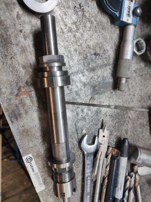
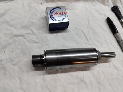
The completed shaft:
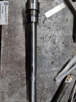
Running it in a single setup gives no room for any more error that the spindle bearings on the lathe can give.
For some silly reason I didn't take any photos of making the rotating spacers/labyrinth seals. They're straightforward machining, anyhow.
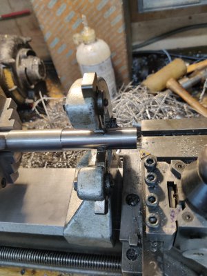
On to the housing! This is a fair challenge. For the spindle to function correctly within it, each end has to be concentric and true to the other. I opted to tackle the critical end first, plus every single other op I could in this initial setup. No place for a tailstock support during boring ops, so out comes the steady rest right after the outside is brought to 40mm:
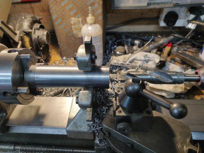
It's too deep for small drills, so I opted to narrow the point on a blacksmiths drill and go for it blind:
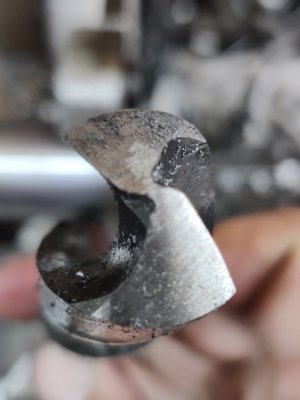
This was far more successful than I had even hoped, with the drill requiring very little pressure to advance. It punched a 22mm hole 100mm deep true enough that I didn't even bother to go in after with the boring bar. The section that's left that size is just a clearance hole, not a working surface. Standard boring practice here using the "balanced cuts" method:
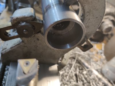
Thread 32tpi
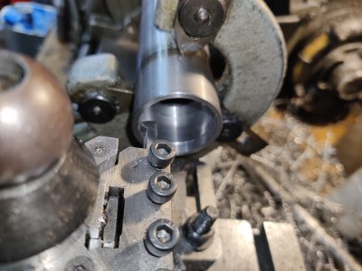
I know, I know. I'm working in metric, but have a confounded English lathe with no provision for metric gearset. These parts will only ever be used with themselves, so whatever. Don't judge
With the outside machined, the inside bored, bearing seats cut and threads cut for the end cap, the only thing left to do was part it off:
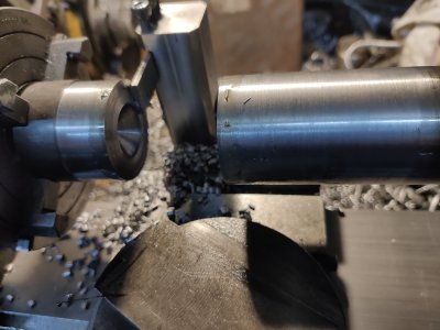
I LOVE my rear-mount parting holder. Parting ops are now an absolute doddle, even deep ones. I don't even give it a second thought.
One end done:
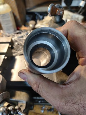
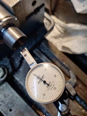
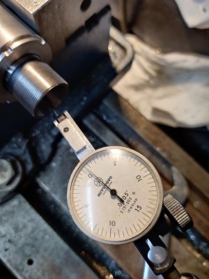
Indicate, indicate, indicate....
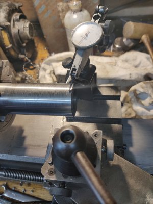
I got it running true within 5 tenths each end. My lathe bearings aren't goo enough to achieve better apparently.
More boring and threading later:
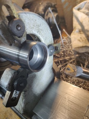
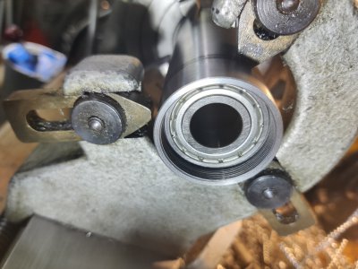
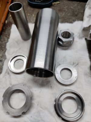
Making up the end caps:
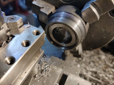
Only intersting op here is trepanning the labyrinth groove. Oh, and a threaded in reverse with the tool correct way up, but from the rear of the part. Works well.
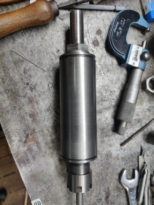
Test fit:
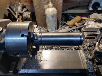
With it run up like that just on the thread I still got 5 tenths runout on the outside. I'll take that!
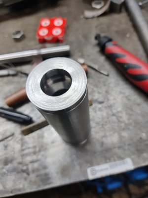
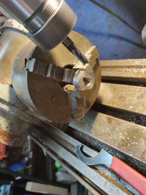
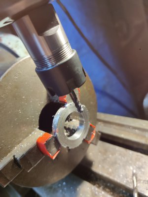
I need to pop it in the mill to cut some pin spanner holes.
That brings us up to date. I still have to do some careful measuring and manufacture the spacer (purple in the cutaway above), then give everything a seriously thorough deburr and clean before thinking about fitting bearings and assembling. The bearings are not cheap. One slip onto an area that's not perfectly clean and it's a lot of money down the drain. Gotta be perfect first time! There's literally no room for taking it apart and fettling something that's not clearing or whatever. Eeek!
I'll update as things progress.
I decided to design a modern spindle with an ER20 taper, precision collets for which are readily and cheaply available and it allow for far more flexibility in tool and mounting choice than the simple home-made affairs suggested. The original design uses a pair of 13mm ID magneto bearings back to back and preloaded with springs. I should admit at this point that I have manufactured a spindle to plans, but found myself thinking it looked a little weedy. After much musing, and having re-watched Robin Renzetti's excellent video on spindle rebuilding/design, I decided to essentially miniaturise the Bridgeport design. At the business end this uses a pair of precision angular contact bearings, matched from factory (DB ground) to have the correct preload when placed back-to-back, supported at the other end by a standard roller bearing - in this case, dealing with the lateral load from the pulley. The original spindle case ends up around 35mm, but there's enough meat in the casting it gets held in for a 40mm case. The obvious choice, then, was a Nachi 7003 precision bearing pair, each measuring 17x35x10mm.
Having decided on the bearing arrangement, I turned my attention to how to manufacture the spindle itself. I can't even buy silver steel stock for the price that even a decent brand ER20 straight shank holder will set you back, let alone drill and bore the centre down the 200mm length! The only sticking point is that only 16mm and 20mm are available - not 17mm. I took a leap of faith that a 20mm shank wouldn't be so hard that I couldn't machine it. As far as I can tell, while it's some kind of tool steel it's not been made particularly hard and while it would eat HSS, machined really nicely with carbide. But we're getting ahead of ourselves....
After much pondering, I came up with this:

It's literally a miniature clone of the Bridgeport spindle, though I omitted the spacers they use between the bearing pair. No doubt this is for extra stiffness, but I doubted my ability to make two perfectly length matched spacers having no surface or cylindrical grinder, so opted for simply using the bearings back-to-back as the manufacturer recommends and doubt I'll regret my decision. I was too lazy to model threaded portions, so red patches mark interference fits and represent fine pitch threads.
On to construction:
Helpfully, the manufacturing process leaves a chamfer in the end of the Er20 holder. I planned to use this to steady the end and made up an arbor which fit the taper at the other end.

With this arrangement I could finish every operations I needed to do in one setup. Great for critical concentricity:

Straight off the tool. Gorgeous. Gotta love hard turning!

You can see the two journals slightly proud. It took some breaking free of the taper, which I'll take as a sign of a good fit. The journal for the single supporting bearing is left a heavy sliding fit, with the journal for the main pair more of a very light interference fit. This eases assembly tremendously, as does the relief between the two journals. You really, really don't want to be fighting your bearings the whole way down when assembling!
The completed shaft:

Running it in a single setup gives no room for any more error that the spindle bearings on the lathe can give.
For some silly reason I didn't take any photos of making the rotating spacers/labyrinth seals. They're straightforward machining, anyhow.
On to the housing! This is a fair challenge. For the spindle to function correctly within it, each end has to be concentric and true to the other. I opted to tackle the critical end first, plus every single other op I could in this initial setup. No place for a tailstock support during boring ops, so out comes the steady rest right after the outside is brought to 40mm:

It's too deep for small drills, so I opted to narrow the point on a blacksmiths drill and go for it blind:

This was far more successful than I had even hoped, with the drill requiring very little pressure to advance. It punched a 22mm hole 100mm deep true enough that I didn't even bother to go in after with the boring bar. The section that's left that size is just a clearance hole, not a working surface. Standard boring practice here using the "balanced cuts" method:

Thread 32tpi

I know, I know. I'm working in metric, but have a confounded English lathe with no provision for metric gearset. These parts will only ever be used with themselves, so whatever. Don't judge
With the outside machined, the inside bored, bearing seats cut and threads cut for the end cap, the only thing left to do was part it off:

I LOVE my rear-mount parting holder. Parting ops are now an absolute doddle, even deep ones. I don't even give it a second thought.
One end done:

Indicate, indicate, indicate....

I got it running true within 5 tenths each end. My lathe bearings aren't goo enough to achieve better apparently.
More boring and threading later:


Making up the end caps:

Only intersting op here is trepanning the labyrinth groove. Oh, and a threaded in reverse with the tool correct way up, but from the rear of the part. Works well.
Test fit:

With it run up like that just on the thread I still got 5 tenths runout on the outside. I'll take that!

I need to pop it in the mill to cut some pin spanner holes.
That brings us up to date. I still have to do some careful measuring and manufacture the spacer (purple in the cutaway above), then give everything a seriously thorough deburr and clean before thinking about fitting bearings and assembling. The bearings are not cheap. One slip onto an area that's not perfectly clean and it's a lot of money down the drain. Gotta be perfect first time! There's literally no room for taking it apart and fettling something that's not clearing or whatever. Eeek!
I'll update as things progress.


