There are dozens of off-the-shelf panel mounted RPM displays available on line. I suppose anyone of them would do as long as there were circuit details available - like what encoder to use etc. Many of them come with magnetic (hall effect?) sensors all for around 5 or 6 dollars.
The suggestions in your second and third paras are a bit over my head, I'm afraid. I've never owned a signal generator or a scope for that matter so it will just have to be a cardboard disk on the end of a drill - more my level. I have assembled kits using 555 timers in the past. As you say, one of the cheapest ICs around.
Although I've enjoyed mucking about with practical electronics since I was a kid (I'm 74 now), I never got very far with theory. As for the maths involved. forget it! I can follow a simple circuit diagram to build a PCB but if it doesn't work afterwards, I'm lost - unless it's something obvious like a badly soldered joint or a diode the wrong way round.
Many years ago, I used to get a great kick out of editing single-side PCB artwork on a PC (from an existing circuit) using Protel Autotrax and then plotting the pattern out on a Roland XY pIotter directly onto the copper clad board (I never mastered the photo-mask method). The .3mm fibre pens were etch resistant and produced very clean results. All just .1inch stuff, of course. It was hugely satisfying watching the PCB tracks appear on the board before dropping it straight to the etching bath. After etching, I'd drill the holes by hand with a .7mm drill. I made lots of small gadgets that way. Sadly, I had to give that method up because I couldn't get the plotter pens. If I were doing this stuff now, I'd most likely be looking for a CNC router to produce PCBs.
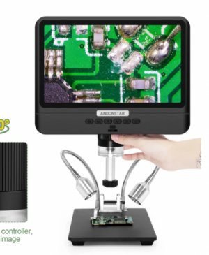
These days, it's just assembly and soldering I really enjoy. Recently, I bought some kits to assemble that used SMD exclusively. I'd only ever assembled through-hole PCBs before this. I had to buy one of these el-cheapo digital microscopes to cope with the .5mm pitch ICs. Great fun learning to solder with a soldering tip like a needle while looking at an LCD screen!
Please excuse the ramble.
The suggestions in your second and third paras are a bit over my head, I'm afraid. I've never owned a signal generator or a scope for that matter so it will just have to be a cardboard disk on the end of a drill - more my level. I have assembled kits using 555 timers in the past. As you say, one of the cheapest ICs around.
Although I've enjoyed mucking about with practical electronics since I was a kid (I'm 74 now), I never got very far with theory. As for the maths involved. forget it! I can follow a simple circuit diagram to build a PCB but if it doesn't work afterwards, I'm lost - unless it's something obvious like a badly soldered joint or a diode the wrong way round.
Many years ago, I used to get a great kick out of editing single-side PCB artwork on a PC (from an existing circuit) using Protel Autotrax and then plotting the pattern out on a Roland XY pIotter directly onto the copper clad board (I never mastered the photo-mask method). The .3mm fibre pens were etch resistant and produced very clean results. All just .1inch stuff, of course. It was hugely satisfying watching the PCB tracks appear on the board before dropping it straight to the etching bath. After etching, I'd drill the holes by hand with a .7mm drill. I made lots of small gadgets that way. Sadly, I had to give that method up because I couldn't get the plotter pens. If I were doing this stuff now, I'd most likely be looking for a CNC router to produce PCBs.
These days, it's just assembly and soldering I really enjoy. Recently, I bought some kits to assemble that used SMD exclusively. I'd only ever assembled through-hole PCBs before this. I had to buy one of these el-cheapo digital microscopes to cope with the .5mm pitch ICs. Great fun learning to solder with a soldering tip like a needle while looking at an LCD screen!
Please excuse the ramble.