Received my PM949 and PM1340GT!!!

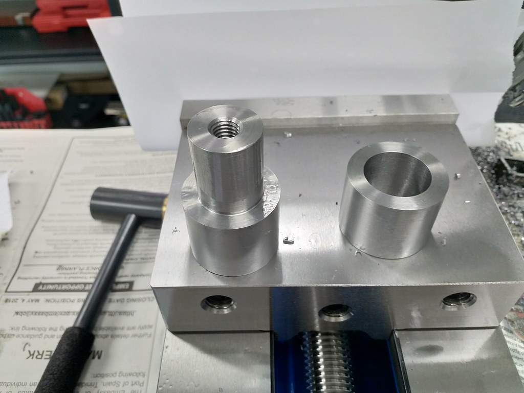
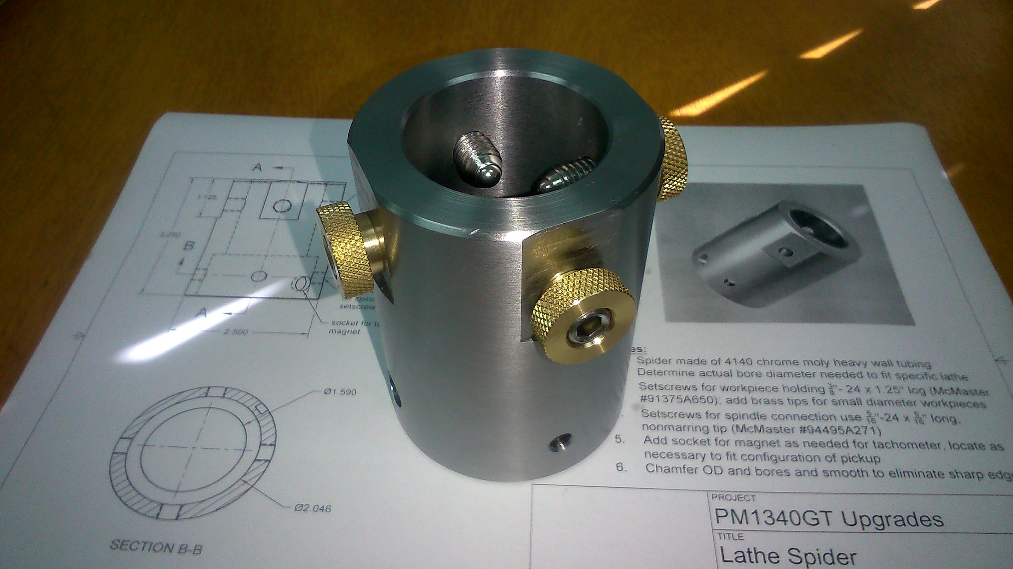
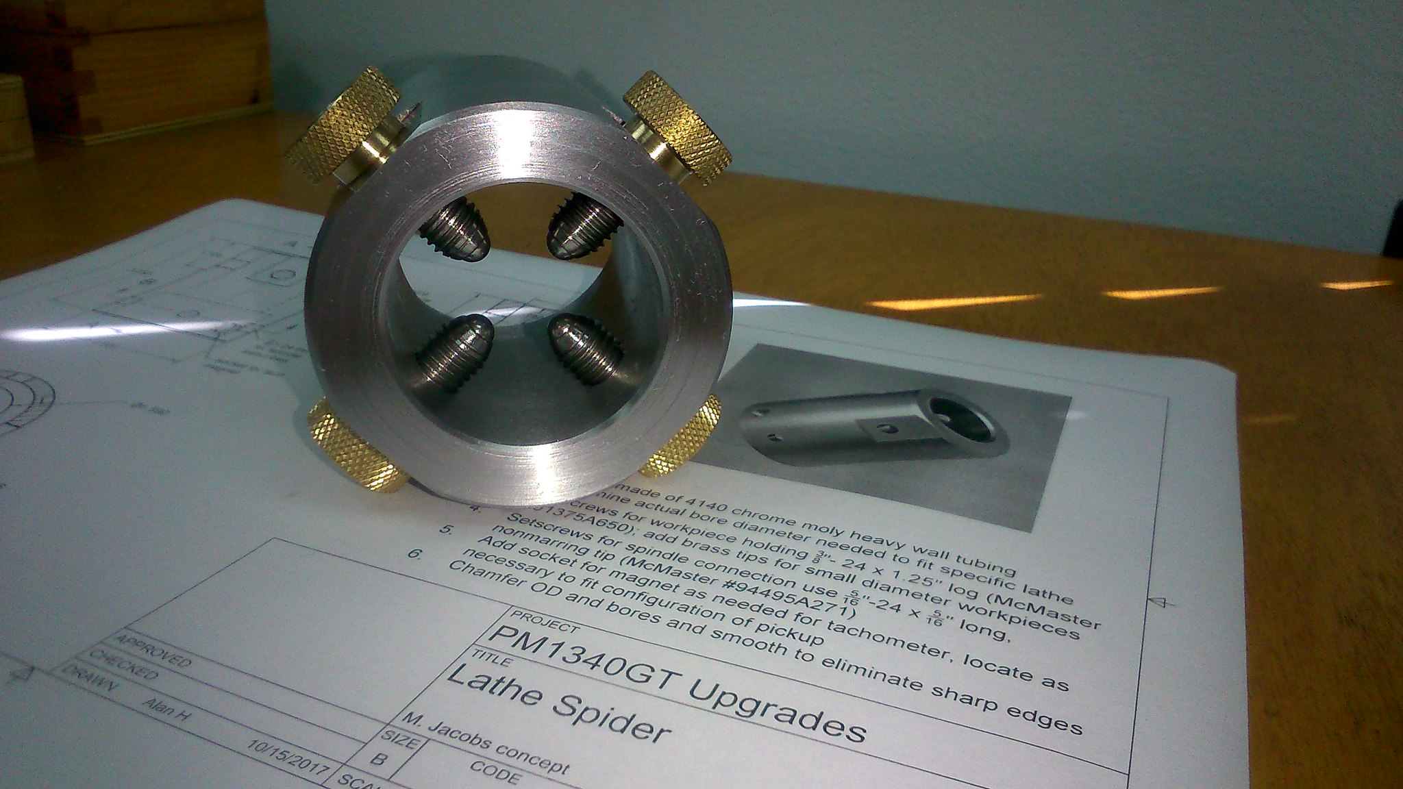
Finished up my Spider for the lathe using Allan's drawings. Thanks for sharing these Allan!

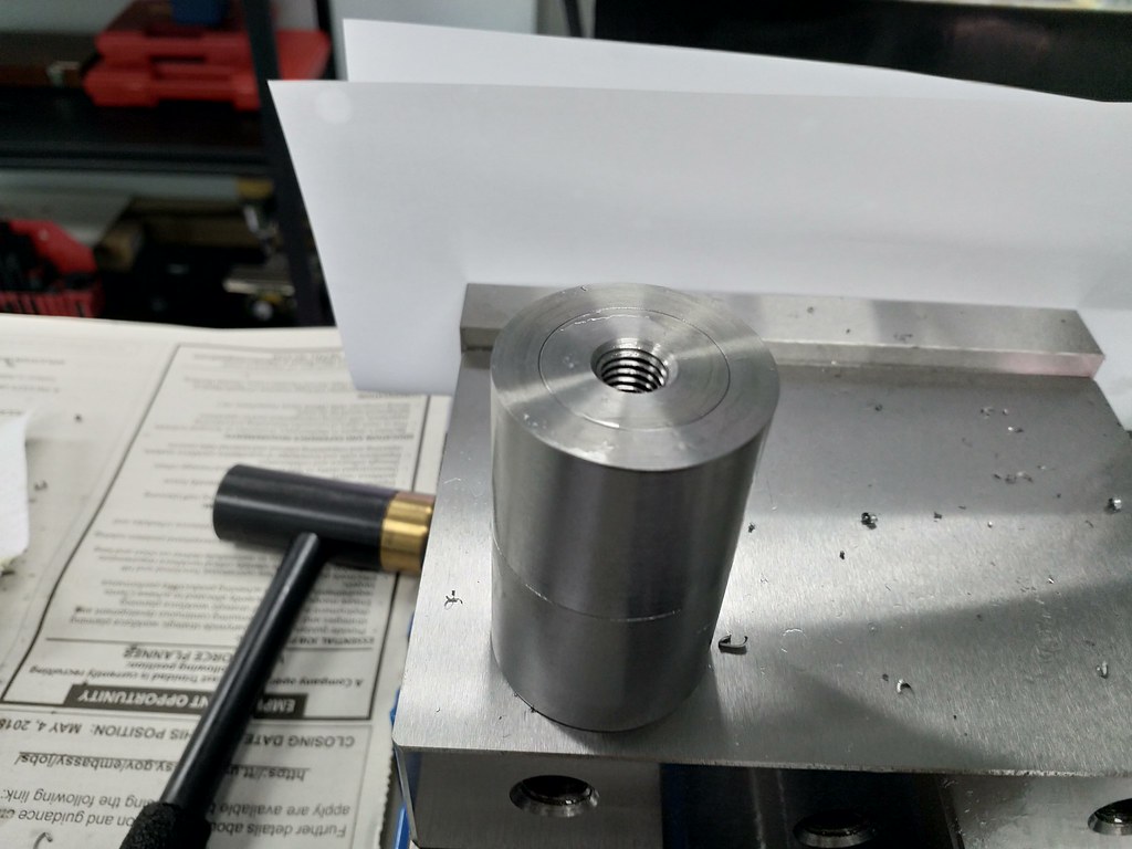
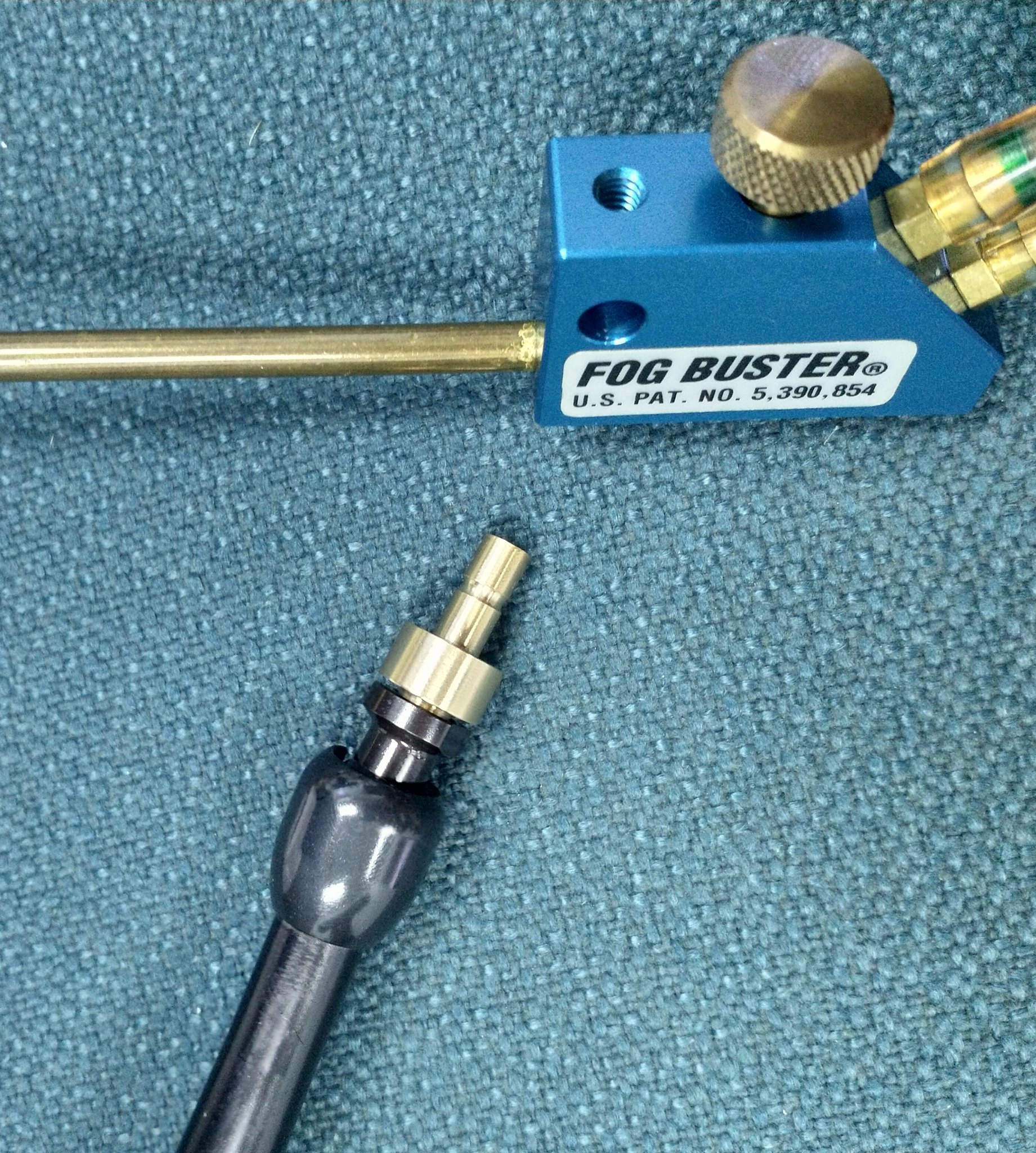
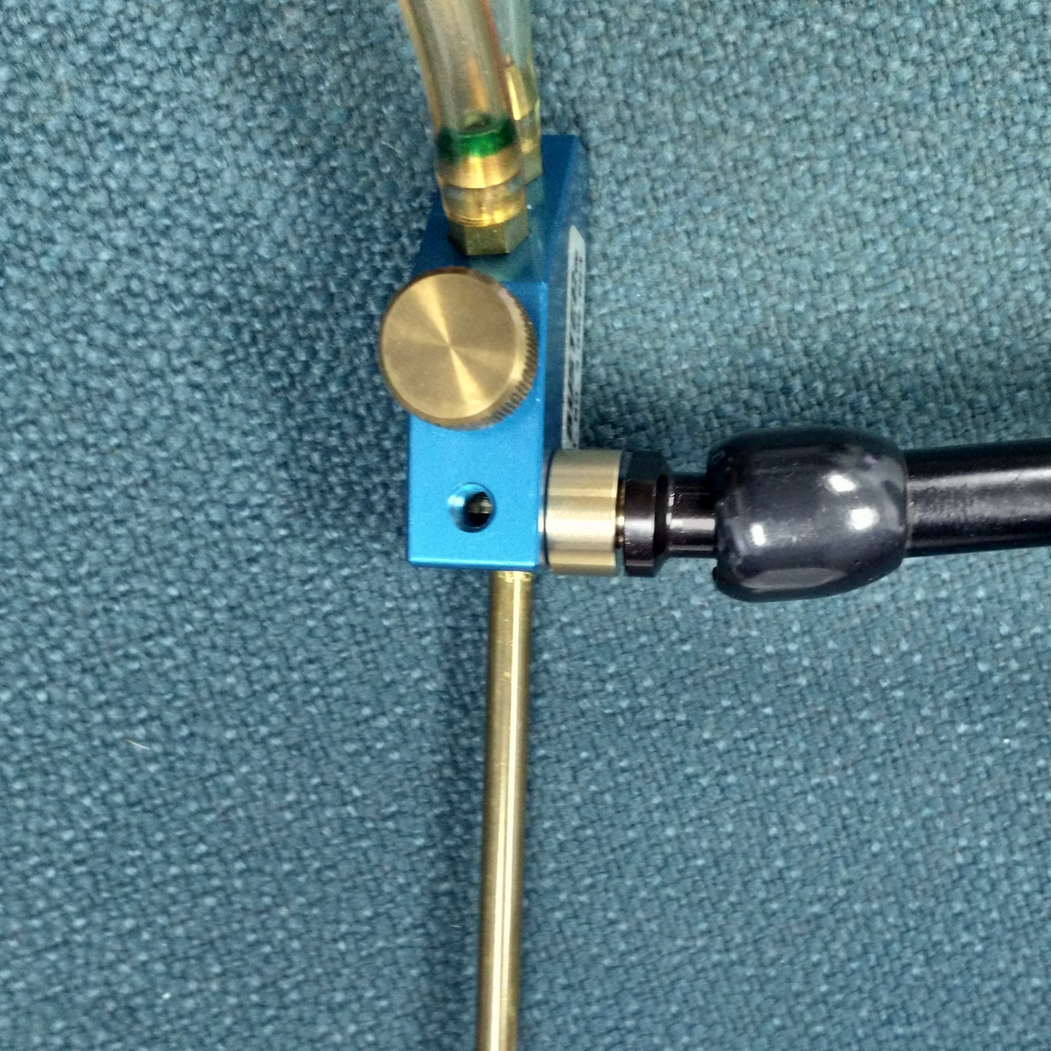
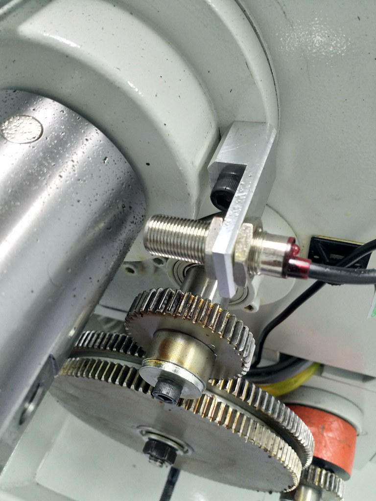
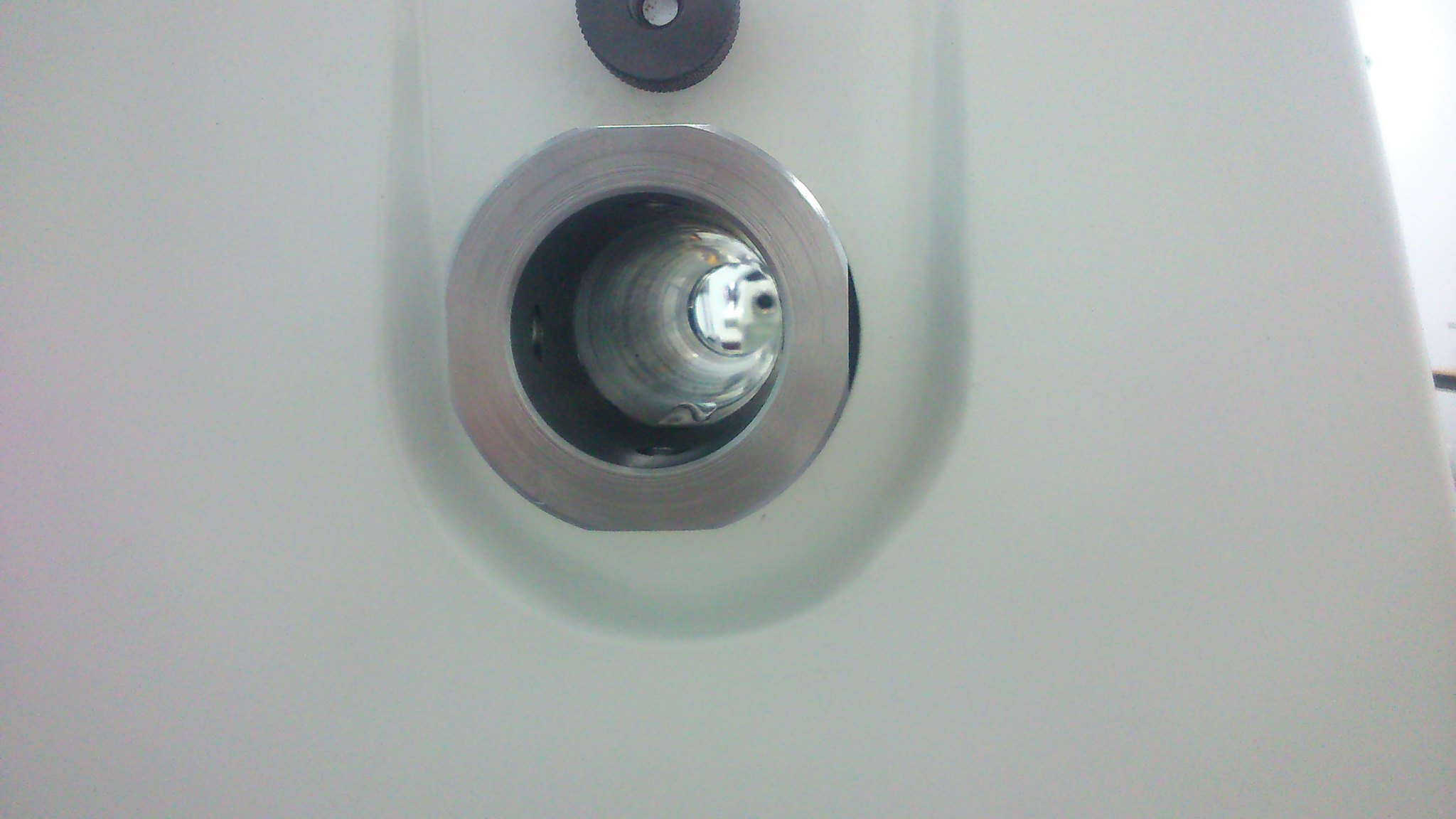
I did use metric hardware instead of what was called out in the drawing. For the adjusting set screws I used M10 with spring loaded ball bearings on the tips. M6 brass tipped set screws were used for mounting to the lathe's spindle. There is a 10mm pocket for the tachometer's magnet. A 3mm hole was drilled thorough the center of this pocket to aid in the removal of the magnet if needed.

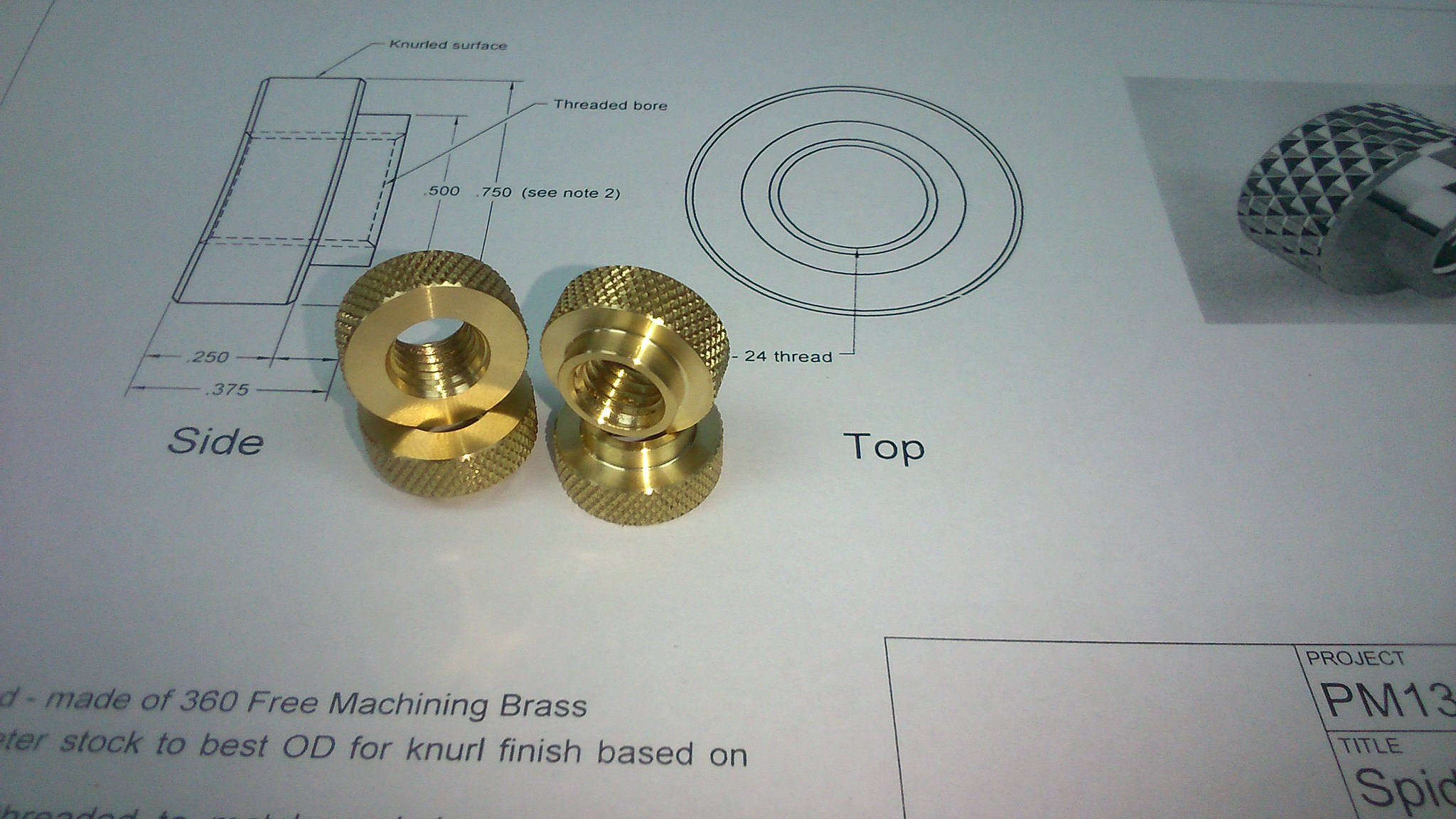
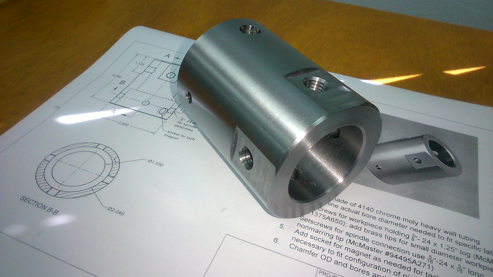
Thumb nuts are made from 360 brass and the spider body from 2.5" 4140 tubing.

27154169467_05f2aba57a_k.jpg


28151321598_201398a497_k.jpg


28151325168_9c734a83a6_k.jpg


41979641772_a7e277d29d_k.jpg


42024638611_58b3ff0e40_k.jpg


Chevy
 
Looking good Chevy, nice work. I needed to bore my cover to fit the spider, I mounted it on my mill and used a boring head.
Mark
 
Chevy: I"m coming around to your thoughts about putting the control panel on the right front off of the knee rather than where I'd planned off the head. Any second thoughts about placement or issues with it as I'm planning on a very similar layout for the control switches while mounting my DRO and Tach on the left side of the head (where the original motor control switch was mounted). Thanks for the help so far.
Alex
 
Hey Alex, I've been using that machine almost every day for most of this year and I'm very happy with the location of my controls.

Main controls on the knee
Tachometer and emergency stop where the original drum switch was on the head

I actually recently started to install my DRO for this machine and mounted the display on an adjustable arm that mounts on the ram using the thread that the lifting eye goes in. I'll take a picture for you tomorrow.

Chevy
 
Hey Alex, I've been using that machine almost every day for most of this year and I'm very happy with the location of my controls.

Main controls on the knee
Tachometer and emergency stop where the original drum switch was on the head

I actually recently started to install my DRO for this machine and mounted the display on an adjustable arm that mounts on the ram using the thread that the lifting eye goes in. I'll take a picture for you tomorrow

Thanks for the quick response Chevy, I think I'm going to set up my controls very similar to you off the knee on the right side. I am wondering about the location of the emergency stop - why not on the panel off the knee? I imagine reaching across the machine to reach it beside the head (I'm only 5'5" so it's a reach if I'm in a rush) which seems counter-intuitive to me. You must have had a reason and I'm a novice so I'm interested.
Thanks again.
Alex
 
So these are some of the things I've been working on since my last update.

Installed DRO display on an adjustable arm. The arm mounts on the 3/4-10 threaded hole on the ram.

43484080074_6e3a90c66c_k.jpg


43296112865_02f0c5ecf0_k.jpg


42394259600_040058e9ac_k.jpg


The arms are 30mm square mild steel tubing that was notched to fit the round pieces. The round pieces were turned/bored on the lathe and welded in place.

Hinge pieces

28587050027_c177f341f6_b.jpg


42757294634_bd3f369ffe_b.jpg


Notched Tubing

28587090617_aeb5ae8c09_b.jpg


Welded

44153937442_542c0afc7e_k.jpg


The delrin washers and aluminum caps were also made on the lathe.

44153935772_75b211d458_k.jpg


FogBuster installed

44153918022_4ebfd04564_k.jpg


The head is installed on a Noga arm for easy positioning

29265203547_418c48cff1_k.jpg


And swings out of the way when not needed

42394256680_e235e79bc8_k.jpg


The brass part is an M8 threaded adapter I made to attach the misting head to the Noga arm.
The aluminum part allows the Noga arm to be mounted to the head of the mill.

42394272110_ae114d64aa_k.jpg


Test fitting the adapter

43484096074_f4bf2bca74_k.jpg


44201983721_edc209b777_k.jpg


The proximity stop that Mark makes for his control system is beautiful. This is my final pass on this M8 thread @ 210RPM utilizing the proximity stop.


The lathe also got a pump oiler to lubricate its QCGB

44153916352_e7a60cac90_b.jpg


I did not make a manifold like Mark, David and Alan did. When I was testing this setup I found that two pulls of this pump was enough to fill the entire gallery with oil. After two pumps I checked the gears inside the QCGB and all the gears had oil dripping on them.

So instead of making a manifold I just ran the Tygon tubing from the pump to the gallery. I lined the base of the gallery with medical gauze secured by magnets at each corner.

The gauze does a few things:

1. Helps distribute the oil throughout the entire gallery
2. Acts as a time release for the oil. Without it the oil just drains out in a very short space of time
3. Acts as a filter for the oil ports.

44153894442_5a666d4fa5_b.jpg


Lathe Tachometer sensor mount

30334636368_578360cfda_b.jpg


Alex,

The only reason I mounted my emergency stop on the head was because it just felt more natural to me to reach up and hit it in case of an emergency.

Chevy
 
VERY slick Chevy, I too love that proximity switch Mark builds into his lathe controls, it makes internal threading a joy without having to thread in reverse to be safe and consistently stops within less than .0005" and usually within 2 or 3 ten thou. Given my height I think my emerg stop is going on the panel off the knee, I need a step ladder to do a belt/pulley change for mine so that position is a bit too high to work for me.
I do love the DRO display set up tho' and might copy that and might put my tach on it as well along the line of what I did with my lathe DRO.

20171223_214232 (1).jpg


I'm thinking that that is one place to look for all my digital info and I really like your idea of that adjustable arm - any decent monitor mount would work also with minor adaptation to fit the bolt hole you used. Interesting thoughts on the lube set up for the quick change gear box - I have picked up a pump and tubing to install and planned to make a header with 1/2" copper pipe and had planned to solder in a 1/2 dozen or so 1/8" copper tubes to the 1/2 copper header to distribute the oil but I like simple so might try a version of what you did - Great Idea.
My tach mount is pretty mickey mouse compared to what you did, I'd no Mill when I hooked it up (still don't have on running!) and simply hammered one out of 1/8" MS plate - works but looks a bit tacky!

IMG_0463.JPG


Do you have Marks proximity sensor for the back gear on your set up? The idea of having forward always forward and reverse always reverse appeals to me.

Must say it's hard to believe you actually do the work in you shop, that place always looks so CLEAN and neat, VERY impressive set up! Thanks for posting and responding to questions.
Alex
 
Sounds great Alex,

The most important thing about placement of controls is the it's comfortable to the operator.

I don't have Mark's proximity sensor for back gear, for me it's not a big deal to switch the motor to reverse.

Anyone that visits the shop always ask if I do actually work there lol. I like starting my day in a clean shop, so the last hour of everyday I clean up and oil down my tools.

Chevy
 
Back
Top