

- Joined
- Feb 1, 2015
- Messages
- 9,621
I have often wondered about the feasibility of reconfiguring AC induction motors for a different voltage or rotation when the winding taps aren't readily available. I have several 1/2 hp, 208/220 single phase capacitor start motors that I picked up on the cheap some years ago which had been sitting un my barn for lack of a suitable application and I thought this would be a good learning opportunity.
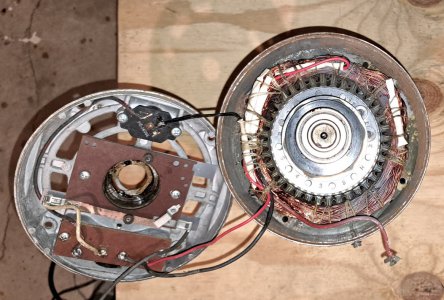
The motors have a 56C frame and made by two different manufacturers. They had been modified to bring the start winding outside he motor so they could be reversed externally. Motor #1 was made by Doerr and motor #2 was made by Robbins & Meyers. U started on the Doerr motor first.
The first step was making witness marks on the shaft end of the frame for reassembly purposes as the holes for the assembly screws were blind. I pulled the back end cap off and then removed the shaft end cap, along with the armature. To make working easier, I removed the terminal board, the thermal cutout switch, and the centrifugal switch from the end cap.


The motor opened up, the windings exposed
The next step was to identify the windings. For some reason, the centrifugal switch contact were both brought outside the motor. A lead from the start capacitor was also brought outside, along with connections from various windings. At that point, I couldn't determine what the internal connections were. The start capacitor was rated for 220 vac which led me to believe that the start winding followed the more typical convention of connecting to the junction of the two run windings.

The lacings and insulation removed form the splices
I cut the lacing harness and removed it which made five winding connections visible. Two were connected to the terminal board and appeared to be the line connections. One was connected to a capacitor lead. The remaining two had no leads connected. I carefully pulled the insulation sleeves off the connections which revealed that the one of the latter two connections simply connected two ends of windings while the other had three winding ends connected together. Measurements of wire diameters revealed that the run windings were .035" diameter while the start winding was .023" diameter. The connection involving the two wires joined .035", indicating that they were run windings. The other winding connected the start winding to the junction of two run windings. This latter connection was a bit of a mystery as one would normally not expect to find three run windings in a single phase induction motor. A resistance check implied that the two wire connection was just there for manufacturing convenience and could be ignored as the two windings just made up one side of the run winding.
The figures below depict the motor configurations for 208/220 volt and 120 volt operation. In either, the line is connected to L1 and L2. Connections S1 and S2 connect the start winding to the run windings with the configuration determining the direction of rotation.

Normally, a 220 volt capacitor start motor runs the start winding on the junction of the two run windings for 110 volt operation. Reversing the direction just requires connecting the second lead from the capacitor to one or the other of the line connections ( through the centrifugal switch); i.e. S1 to either L1 or L2. On the other hand, in a 110 volt induction motor the start winding/capacitor/ centrifugal switch are wired across the line and motor reversal is accomplished by reversing the connections of the start circuit, i.e. S1 to L1 and S2 to L2 or S1 to L2 and S2 to L1.
To convert the motor from 220 volt operation to 110 volt operation, the three wire connection between W2, W3, and W4 had to be broken, separating the two halves of the run winding and the start winding respectively Note that the windings have a sense, depicted by the dot at the top of each winding. It is important that the winding sense be maintained when reconfiguring.
The OEM connections were made by means of small brass ferrules crimped on the wires. For those connections which required modifications, the wires were clipped just below the ferrule. The enamel insulation was removed by clamping the wire about 1/2" from the end with needle nosed pliers to act as a heat sink and burning the insulation with a butane microtorch. The burnt insulation was gently scraped away with a knife blade, followed by burnishing with a Scotch Brite pad. To make the connections, the bare wires were tightly twisted together to make a mechanical connection. If a breakout lead was needed, about 3/4" of insulation was stripped and the bare strands wrapped around the twisted wires. The resulting assembly was then soldered with high melting point solder and the OEM insulating sleeve fitted over the connection. With the connections still exposed, continuity was confirmed by measuring resistance with a multimeter.
To fix the sleeves in place, a length of heat shrink tubing was fit over the sleeve. While the heat shrink was still hot, the tag end was pinched together with two fingers to seal the connection. The final step was to relace the motor windings. I used some nylon shoemakers thread with has a fairly high tensile strength. Braided fishing line would be a good alternative. I made a lacing needle by bending six inches of 18 awg copper wire in half. opening up the end to make an eye, and bending the resultant into a "c" shape. The lacing was threaded under the windings and the previous thread to make the harness. When the lacing was completed, it was fixed in place with cyanoacrylate glue. Alternative fixative would be varnish or epoxy but the cyanoacrylate was fast and easy.
The remaining lead from the capacitor was fitted with a female spade connector and connected to the centrifugal switch. A lead from one of the terminals on the terminal board was connected to the other contact on the centrifugal switch. The terminal board was reconfigured with external connections for L1, L2, S1 and S2 and jumpers with spade connectors were added to make configuring the direction of rotation simple.
photo 4
windings reconfigured, connections insulated, and windings relaced. Ready to button up
The shaft end plate and armature were inserted and lined up with the witness marks. The other end plate was put in place, making sure that all wires were clear of the of the rotating parts and the four screws fastened. The capacitor was connected and fit into its housing and the housing was fastened to the frame. This completed the assembly. The motor was connected to the 120 volt line and tested for forward and reverse operation.
The second motor was configured slightly different in that all connections between the separate windings, eight in all, were brought out to crimp connectors. In order to identify the windings, I connected a 12 volt battery across the two line terminals and measured the voltages at each of the connections. I did the same for the two start windings. With the windings identified I proceeded as I had done with the first motor.
This motor had tape rather than insulating sleeves for the crimp connector insulation so I used some Teflon tape (not the plumbing kind) for the primary insulation followed by the heat shrink tubing. The wiring was then laced as for the first motor. The terminal board on this motor only had two terminals for the line connections so I added two more terminals for the start circuit and finished it as for the first motor. The motor was then reassembled and tested for operation.
Motor #3 Another motor that I had was on a small vacuum/compressor. It was a 230 volt permanent split capacitor motor. It is similar to a capacitor start motor in that it has a start winding with a capacitor in series with the winding. It differs in that the winding doesn't switch out once the motor reaches running speed. This type of motor is often used on small appliances as it provides a higher torque than a split phase motor but without the added complexity of a centrifugal switch.
The original configuration consisted of two sets of four windings wired in series. The main winding string was connected to the 230 volt line while the start winding was connected in series with a capacitor and the string was then connected to to the 230 volt line. To convert the motor to 120 volt operation, the windings were disconnected between the 2nd and 3ed windings resulting in four sets of two windings in series. The main and sets were then respectively wired in parallel for 120 volt operation..
After disassembling the motor, the string lacing that secured the windings and insulation were removed to reveal the various connections. The identification of the terminal windings was straightforward, consisting of a brown and a blue wire which connected to the mains and two red wires which connected to the external capacitor.
Determination of the inter-pole wires required some detective work. Starting with the blue wire, the main and start windings were connected together The first and second poles windings would remain intact as would the third and fourth pole windings. The fourth pole main winding would be connected to the blue wire while the fourth pole start winding would be connected to the capacitor.
A visual examination located the wires connecting the various poles which happened to be on the opposite end of the frame. The connection between the 2nd and 3rd main winding was fairly obvious but the start windings were buried to the extent that a visual tracing wasn't certain. To identify the winding interconnections, I connected a set of windings to a 12 volt battery and scraped a bare spot on each of the suspect wires. By measuring the voltage drop at each interconnection, I could positively identify the correct sequence. Once the wires were identified, I coated the bare spots with urethane two coats of urethane varnish to restore the insulation and split the string into two equal halves. Measuring the resistance of each of the two winding sets verified that I had done this correctly.
Next, I had to connect leads to the ends of these wires. I removed the plastic sleeve from a ring connector and cut the termination off leaving the bare ferrule. After inserting the wires, I crimped the ferrule tightly to secure the wires. Then I soldered the connection with high melting point solder and covered with two pieces of shrink wrap tubing. The motor had holes through the laminations for tie rods but didn't use them so I threaded the four leads through one of the holes to bring all the motor connections to the same side.
Next up was lacing the windings. I used shoemaker's Nylon cord for the lacing but a braided Nylon fishing or netting line would work as well. I worked with six ft. lengths, tying an new length to the old as I progressed. To pull the lacing through, I made a small hook from a length of wire feed wire.

The relacing tool. I attached to a key ring to make it easier to find on the bench.
I secured the end of the lacing and working from the outside, slid the hook under the winding and pulled a loop of the lacing through. Then I brought the tag end over the top and wrapped it through the loop three times. As the lacing was tightened to the inside, this made a secure knot for that wrap. I continued this process around the entire perimeter, including any connections in the wrap. To permanently fix the windings, I put a dab of super glue on each knot and followed with a coating of epoxy.


The two ends of the motor, reconfigured and relaced, ready for reassembly
Before reassembly, I checked all the windings for continuity. Satisfied, I reconfigured the windings for 120 volt operation and reassembled the motor, making sure that the armature turned freely. Then I connected the capacitor and hooked up a test lead plugged it in. Success! The old 6 mfd capacitor was no longer suitable for 120 volt operation so starting torque was anemic. Increasing to 24 mfd provided ample starting torque even at full load. All in all, this was an interesting exercise, demonstrating the ability to reconfigure an induction motor to meet you specific needs. It will pump down to 28" Hg but I'll need to come up with a ballast tank for pressure operation for a steady pressure. Supposedly, the free air flow is 3.5 cfm which is fairly good for a little unit like this.

Reassembled motor, reconfigured for 120 volt operation
The motors have a 56C frame and made by two different manufacturers. They had been modified to bring the start winding outside he motor so they could be reversed externally. Motor #1 was made by Doerr and motor #2 was made by Robbins & Meyers. U started on the Doerr motor first.
The first step was making witness marks on the shaft end of the frame for reassembly purposes as the holes for the assembly screws were blind. I pulled the back end cap off and then removed the shaft end cap, along with the armature. To make working easier, I removed the terminal board, the thermal cutout switch, and the centrifugal switch from the end cap.
The motor opened up, the windings exposed
The next step was to identify the windings. For some reason, the centrifugal switch contact were both brought outside the motor. A lead from the start capacitor was also brought outside, along with connections from various windings. At that point, I couldn't determine what the internal connections were. The start capacitor was rated for 220 vac which led me to believe that the start winding followed the more typical convention of connecting to the junction of the two run windings.
The lacings and insulation removed form the splices
I cut the lacing harness and removed it which made five winding connections visible. Two were connected to the terminal board and appeared to be the line connections. One was connected to a capacitor lead. The remaining two had no leads connected. I carefully pulled the insulation sleeves off the connections which revealed that the one of the latter two connections simply connected two ends of windings while the other had three winding ends connected together. Measurements of wire diameters revealed that the run windings were .035" diameter while the start winding was .023" diameter. The connection involving the two wires joined .035", indicating that they were run windings. The other winding connected the start winding to the junction of two run windings. This latter connection was a bit of a mystery as one would normally not expect to find three run windings in a single phase induction motor. A resistance check implied that the two wire connection was just there for manufacturing convenience and could be ignored as the two windings just made up one side of the run winding.
The figures below depict the motor configurations for 208/220 volt and 120 volt operation. In either, the line is connected to L1 and L2. Connections S1 and S2 connect the start winding to the run windings with the configuration determining the direction of rotation.
Normally, a 220 volt capacitor start motor runs the start winding on the junction of the two run windings for 110 volt operation. Reversing the direction just requires connecting the second lead from the capacitor to one or the other of the line connections ( through the centrifugal switch); i.e. S1 to either L1 or L2. On the other hand, in a 110 volt induction motor the start winding/capacitor/ centrifugal switch are wired across the line and motor reversal is accomplished by reversing the connections of the start circuit, i.e. S1 to L1 and S2 to L2 or S1 to L2 and S2 to L1.
To convert the motor from 220 volt operation to 110 volt operation, the three wire connection between W2, W3, and W4 had to be broken, separating the two halves of the run winding and the start winding respectively Note that the windings have a sense, depicted by the dot at the top of each winding. It is important that the winding sense be maintained when reconfiguring.
The OEM connections were made by means of small brass ferrules crimped on the wires. For those connections which required modifications, the wires were clipped just below the ferrule. The enamel insulation was removed by clamping the wire about 1/2" from the end with needle nosed pliers to act as a heat sink and burning the insulation with a butane microtorch. The burnt insulation was gently scraped away with a knife blade, followed by burnishing with a Scotch Brite pad. To make the connections, the bare wires were tightly twisted together to make a mechanical connection. If a breakout lead was needed, about 3/4" of insulation was stripped and the bare strands wrapped around the twisted wires. The resulting assembly was then soldered with high melting point solder and the OEM insulating sleeve fitted over the connection. With the connections still exposed, continuity was confirmed by measuring resistance with a multimeter.
To fix the sleeves in place, a length of heat shrink tubing was fit over the sleeve. While the heat shrink was still hot, the tag end was pinched together with two fingers to seal the connection. The final step was to relace the motor windings. I used some nylon shoemakers thread with has a fairly high tensile strength. Braided fishing line would be a good alternative. I made a lacing needle by bending six inches of 18 awg copper wire in half. opening up the end to make an eye, and bending the resultant into a "c" shape. The lacing was threaded under the windings and the previous thread to make the harness. When the lacing was completed, it was fixed in place with cyanoacrylate glue. Alternative fixative would be varnish or epoxy but the cyanoacrylate was fast and easy.
The remaining lead from the capacitor was fitted with a female spade connector and connected to the centrifugal switch. A lead from one of the terminals on the terminal board was connected to the other contact on the centrifugal switch. The terminal board was reconfigured with external connections for L1, L2, S1 and S2 and jumpers with spade connectors were added to make configuring the direction of rotation simple.
photo 4
windings reconfigured, connections insulated, and windings relaced. Ready to button up
The shaft end plate and armature were inserted and lined up with the witness marks. The other end plate was put in place, making sure that all wires were clear of the of the rotating parts and the four screws fastened. The capacitor was connected and fit into its housing and the housing was fastened to the frame. This completed the assembly. The motor was connected to the 120 volt line and tested for forward and reverse operation.
The second motor was configured slightly different in that all connections between the separate windings, eight in all, were brought out to crimp connectors. In order to identify the windings, I connected a 12 volt battery across the two line terminals and measured the voltages at each of the connections. I did the same for the two start windings. With the windings identified I proceeded as I had done with the first motor.
This motor had tape rather than insulating sleeves for the crimp connector insulation so I used some Teflon tape (not the plumbing kind) for the primary insulation followed by the heat shrink tubing. The wiring was then laced as for the first motor. The terminal board on this motor only had two terminals for the line connections so I added two more terminals for the start circuit and finished it as for the first motor. The motor was then reassembled and tested for operation.
Motor #3 Another motor that I had was on a small vacuum/compressor. It was a 230 volt permanent split capacitor motor. It is similar to a capacitor start motor in that it has a start winding with a capacitor in series with the winding. It differs in that the winding doesn't switch out once the motor reaches running speed. This type of motor is often used on small appliances as it provides a higher torque than a split phase motor but without the added complexity of a centrifugal switch.
The original configuration consisted of two sets of four windings wired in series. The main winding string was connected to the 230 volt line while the start winding was connected in series with a capacitor and the string was then connected to to the 230 volt line. To convert the motor to 120 volt operation, the windings were disconnected between the 2nd and 3ed windings resulting in four sets of two windings in series. The main and sets were then respectively wired in parallel for 120 volt operation..
After disassembling the motor, the string lacing that secured the windings and insulation were removed to reveal the various connections. The identification of the terminal windings was straightforward, consisting of a brown and a blue wire which connected to the mains and two red wires which connected to the external capacitor.
Determination of the inter-pole wires required some detective work. Starting with the blue wire, the main and start windings were connected together The first and second poles windings would remain intact as would the third and fourth pole windings. The fourth pole main winding would be connected to the blue wire while the fourth pole start winding would be connected to the capacitor.
A visual examination located the wires connecting the various poles which happened to be on the opposite end of the frame. The connection between the 2nd and 3rd main winding was fairly obvious but the start windings were buried to the extent that a visual tracing wasn't certain. To identify the winding interconnections, I connected a set of windings to a 12 volt battery and scraped a bare spot on each of the suspect wires. By measuring the voltage drop at each interconnection, I could positively identify the correct sequence. Once the wires were identified, I coated the bare spots with urethane two coats of urethane varnish to restore the insulation and split the string into two equal halves. Measuring the resistance of each of the two winding sets verified that I had done this correctly.
Next, I had to connect leads to the ends of these wires. I removed the plastic sleeve from a ring connector and cut the termination off leaving the bare ferrule. After inserting the wires, I crimped the ferrule tightly to secure the wires. Then I soldered the connection with high melting point solder and covered with two pieces of shrink wrap tubing. The motor had holes through the laminations for tie rods but didn't use them so I threaded the four leads through one of the holes to bring all the motor connections to the same side.
Next up was lacing the windings. I used shoemaker's Nylon cord for the lacing but a braided Nylon fishing or netting line would work as well. I worked with six ft. lengths, tying an new length to the old as I progressed. To pull the lacing through, I made a small hook from a length of wire feed wire.
The relacing tool. I attached to a key ring to make it easier to find on the bench.
I secured the end of the lacing and working from the outside, slid the hook under the winding and pulled a loop of the lacing through. Then I brought the tag end over the top and wrapped it through the loop three times. As the lacing was tightened to the inside, this made a secure knot for that wrap. I continued this process around the entire perimeter, including any connections in the wrap. To permanently fix the windings, I put a dab of super glue on each knot and followed with a coating of epoxy.
The two ends of the motor, reconfigured and relaced, ready for reassembly
Before reassembly, I checked all the windings for continuity. Satisfied, I reconfigured the windings for 120 volt operation and reassembled the motor, making sure that the armature turned freely. Then I connected the capacitor and hooked up a test lead plugged it in. Success! The old 6 mfd capacitor was no longer suitable for 120 volt operation so starting torque was anemic. Increasing to 24 mfd provided ample starting torque even at full load. All in all, this was an interesting exercise, demonstrating the ability to reconfigure an induction motor to meet you specific needs. It will pump down to 28" Hg but I'll need to come up with a ballast tank for pressure operation for a steady pressure. Supposedly, the free air flow is 3.5 cfm which is fairly good for a little unit like this.
Reassembled motor, reconfigured for 120 volt operation
Attachments
Last edited: