Reversing motor wiring question?

astjp2

Active User
Registered
Joined
Aug 23, 2013
Messages
970
Ok, so I have this oriental motor that I am going to use to make a carbide sharpening lap from, I want to to be reverseable. How would I wire it uusing the following diagram and switch? I also have 2 each 10Mfd 400vac caps that I can wire in also. Tim1125131352.jpgmotor.jpg

1125131352.jpg motor.jpg
 
Is that a three position switch? You need a center off and a cam in the switch body that will give different contact closures depending on which direction you turn the switch.
 
the simplest would be to put in a dpdt toggle switch IMHO here is an example of the one i used on my mill (http://www.amazon.com/gp/product/B00004WLKA/ref=oh_details_o08_s00_i00?ie=UTF8&psc=1. i will sketch up a diagram on how you have to wire it and post as soon as i can. simply put, you would take the two wires that go to the black and grey from the line/capacitor and deep blue and reverse them through the switch. really pretty simple to do depending on the room you have for wire and switch.
 
I don't see enough contacts or terminals on the switch you have. As Jim said, you need a 3-position switch & all the contacts need to be open in the center position. Probably one of the capacitor leads needs to be open, too, so current doesn't continuously flow through it & one of the motor windings when it should be off. If I could I'd attach a sketch to this reply but I'm using a Linux distro & haven't gotten my printer or scanner to work yet. So, to make things as simple as possible, I'd use a 3-position, 3-pole, double throw [3-position, 3PDT switch with center open] toggle switch with the same voltage rating as the motor uses & 25% higher current rating than the motor requires so it'll last.

With all that said, one power lead [L2] goes to the red motor lead. The first contact needs to switch the deep/dark blue wire between the black & gray motor leads, deep blue & black closed=CCW. The second contact needs to switch the other power lead [L1] to either the black or gray motor leads, L1 & gray closed=CW. The third contact connects power lead, L1, to the cap in either CW or CCW position & open in the center as are the other 2 contacts. I hope this makes sense.
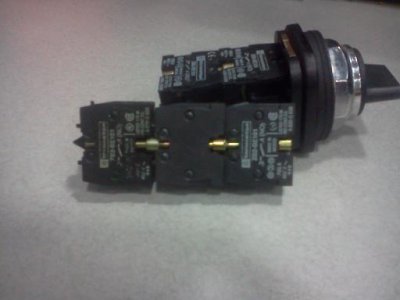
 
That switch goes left on (stack up multiple contacts), off, right on (stack up multiple contacts). I can put on 10 or more sets of contacts for each side. I can install NO or NC switches too. Tim

- - - Updated - - -

I don't see enough contacts or terminals on the switch you have. As Jim said, you need a 3-position switch & all the contacts need to be open in the center position. Probably one of the capacitor leads needs to be open, too, so current doesn't continuously flow through it & one of the motor windings when it should be off. If I could I'd attach a sketch to this reply but I'm using a Linux distro & haven't gotten my printer or scanner to work yet. So, to make things as simple as possible, I'd use a 3-position, 3-pole, double throw [3-position, 3PDT switch with center open] toggle switch with the same voltage rating as the motor uses & 25% higher current rating than the motor requires so it'll last.

With all that said, one power lead [L2] goes to the red motor lead. The first contact needs to switch the deep/dark blue wire between the black & gray motor leads, deep blue & black closed=CCW. The second contact needs to switch the other power lead [L1] to either the black or gray motor leads, L1 & gray closed=CW. The third contact connects power lead, L1, to the cap in either CW or CCW position & open in the center as are the other 2 contacts. I hope this makes sense.

Maybe pencil it out? I think I have it understood but I am not 100% sure. Thanks tim

downsized_1125131630.jpg
 
[That switch goes left on (stack up multiple contacts), off, right on (stack up multiple contacts). I can put on 10 or more sets of contacts for each side. I can install NO or NC switches too. Tim]

Good, then you don't need to get a toggle switch to do this although the wiring might've been a little simpler, I wasn't sure that you could get more contact blocks. The bottom line stays the same: you need enough contact blocks so that you have 3 contacts that are closed only in the left position & 3 that only close in the right position. I'm at a disadvantage since I can't send a sketch but, for the first contact pair, the deep blue wire goes to a contact that closes in the left position & to one that closes in the right position. And be consistent about which side is CW & CCW when you wire it or it won't work. Next, connect the black motor lead to the side you pick to be CW & the gray to the CCW side.

Next, do the same with L1, the power lead that DOESN'T go to the red motor lead; disconnect it from th capacitor & connect it to both an unused contact that closes only in the left position & to one that only closes in the right position. Next connect a jumper from the gray wire on the first contact pair to the next contact pair so it closes with L1 in the CW position. Do the same with the black wire in the first contact pair so it closes with L1 in CCW position.

Now you should have 2 unused contacts, one that closes in each side. Connect a jumper from the power lead on the second pair to the last contact pair in the same manner. Connect the free capacitor lead to one contact opposite L1 then run a jumper from the capacitor lead on this contact to the other contact so the capacitor closes with L1 in both positions. Hope this helps.
 
of coures i have no idea of the room you have to install the switch or get to the wires, but the switch shown earlier would do what you need with this wiring on the DPDT switch.

reversing switch wiring.jpg

i know it is a crude drawing, but should be pretty clear once you figure it out.

reversing switch wiring.jpg
 
Once I get to wiring it, I will take pics and try to lay it out and verify. Thanks Tim
 
maybe this drawing is a little better. easier for you to read and understand. this wiring is based on the switch i posted the link to earlier. used this one on my mini mill and works great. shift it under power for threading routinely.

reversing switch wiring.jpg

reversing switch wiring.jpg
 
Last edited:
This drawing should work as long as this switch has a center off position & has a current & voltage rating that exceeds the operating levels & would be a little easier to hook up than astjp2's 3-position selector switch but it also needs a third pair of contacts that are closed in forward & reverse & open in the center to block current flow through the capacitor when the motor is off. What makes this a bit more difficult is that he wants to use the selector switch & there's probably a large hole already in the cabinet for this switch that's too big for a toggle switch. The drawing looks good & helps show what I was trying to say in my first post here.
 
Last edited:
Back
Top