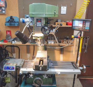
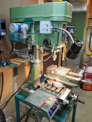
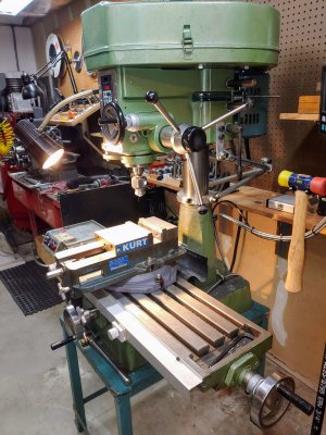
Here are the latest mods/upgrades to my mill. About the only thing left is to add power downfeed which I don't really need but I can't say it won't happen!
Power head lift!
First off, it is kind of awkward to have to reach and turn the crank handle to raise or lower the head, and seriously lacking in the cool factor. I decided I wanted to motorize that function so I started searching online for ideas. I toyed with the idea of adding a step to the motor pulley and using it to drive a lawnmower transmission I have that features an integral clutch, but that seemed too clunky and not cool. I looked at many gear motors on Amazon and eBay for ideas but nothing seemed right, too big, too small, too expensive, etc. I ended up going to a scrap metal yard near me where they save out some interesting items and sell them under the counter, no tax. I ran across a linear actuator that originally came from a Precor treadmill and it looked like it had possibilities. Here is what the one I bought looks like new:
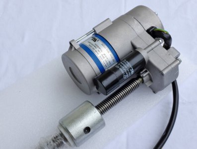
I looked up the model and specs on my phone (MS-1000E, do a Google image search for this number and try "MSI linear actuator" and "MSI UC02" and "treadmill lift incline motor" and look for one exactly like this or a very similar configuration. Other ones could work but I know this one will). It said it could provide 1200 pounds of force at 6" per minute travel plus it's a line voltage AC motor that is reversible. This speed was sounding like it could be in the ballpark for what I wanted to do. I took it home and hooked up some power and it just hummed. I thought it was likely a bad capacitor (the black cylinder in the photo, it has a stud that screws into the casting). I had some trouble finding a replacement that was a match for the specs, size, and stud mounting and I didn't want to spend too much in case it was a dead end. I bought a physically larger one on Amazon with the proper capacity and hooked it up, it ran fine! The motor bearing sounded kind of rough, though.
I disassembled everything to see what I had (should have taken more photos, sorry.) The motor shaft had a helical pinion gear cut into it, driving a 2-step plastic gear which then drives a plastic gear that has a metal hub with a slot to drive a 5mm cross pin in a hole drilled through the output shaft. There were also a bunch of small gears that slowly turn a potentiometer to give some feedback as to the relative travel of the output jackscrew. I tossed all of these along with the pot as I had no use for that stuff. The rough bearing was on the gearbox end of the armature shaft where it also functioned as a thrust bearing, with circlips on the shaft on each side of the ball bearing. It took a fair amount of force to press the bearing out of the casting. I found that was due to the fact that the bore in the housing was only cast to size, not machined, and then swaged over the bearing race to contain it. The new bearing was not a very snug fit, so I managed to hold the housing in my 4-jaw chuck using only 3 jaws and taking a light cut. There was just enough depth to the casting to cut a groove for a 24mm internal retaining ring to contain the bearing. Now the motor ran very quietly. I wanted to make a new output shaft to replace the jackscrew but holding the assembly up to the mill it would have had to stick out too far for a good appearance. The inner end of the shaft went into a blind hole with a bushing and I thought I could have my new shaft come out that side, where there was currently a big boss in line with the jackscrew. I sawed off the boss and machined down the case until I reached the existing bushing hole:
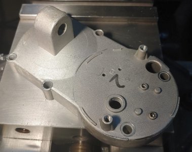
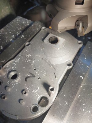
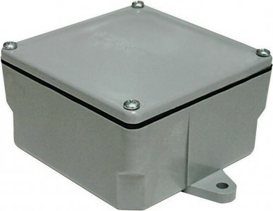
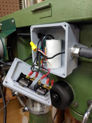
Next, I made a new output shaft that would come out that side of the case. If anyone wants to duplicate what I did, make sure you leave enough length of the small diameter of the shaft so that it can slide in about 6mm extra to allow you to put the cross pin through the shaft on the opposite side of the gear hub and then it can move back over again. I oiled the bushings and greased the gears and put it all together. I made a sheet metal bracket to anchor the motor to the belt guard and mounted it up. I made the bends in the sheet metal less than 90 degrees so I could adjust the in-and-out distance by altering the angles. Then I could put the motor in position and mark where the screw heads were to position the holes to drill. I wired up some 6-conductor wire (fairly small gauge is fine for the low draw of this motor) in the end cover of the motor, bringing out ground, 3 motor wires and two capacitor wires. The motor wiring is simplicity itself: one common wire, one for forward, one for reverse. I found a plastic junction box at Lowes that was perfect, a completely blank box and cover so you can make the needed holes anywhere you like. I brought in a power lead and mounted my existing work light. In the cover I put the switch for the light and a SPDT center-off momentary toggle switch for the lift motor and there was room for the motor capacitor as well. Looks more official than a steel handy box and cover, I think.
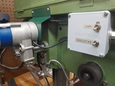
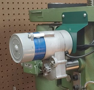
Then came the moment of truth: I made sure the head locking nuts were loose and toggled the switch. Success! It moves the head up or down very quietly and with no fuss, about 3 seconds per inch of travel which seems very comfortable to me. It doesn't strain a bit, going up is about the same speed as going down. My total out of pocket: for the motor $5 (I already had a bearing), the box $15, the capacitor $9 and the momentary switch (less than $2 at Amazon, free shipping). I am very pleased, it definitely has the cool factor now!
Next: 3 phase motor and VFD
Changing speeds on my mill is a pain, especially since I have 3 belts instead of two as most of you do. As a result, usually the speed I use is whatever is already set up. I saw a guy on my local Craigslist offering 3-phase motors and VFDs for mills, lathes, etc. He wanted $420 for a setup, with not that strong of a motor (all new). That got me thinking and on Amazon I found several VFDs that were capable of up to 3HP and I ordered my choice. On my local OfferUp I found a 3HP Reliance 3 phase 1740 RPM motor coupled to a hydraulic gear pump that all looked nice in the photo. The problem was, it had been listed for 8 months! My biggest complaint about OfferUp is that things never expire! It worked in my favor this time, though, as he still had it. He lived about an hour away but was planning a trip my direction, so $60 and a short drive later I had a great motor. I thought maybe the pump would have some value but it turned out someone had crudely ground the shaft down a little bit, so bad luck there (the pump was otherwise perfect). It also came with a manual starter which I used as a power switch for the VFD.
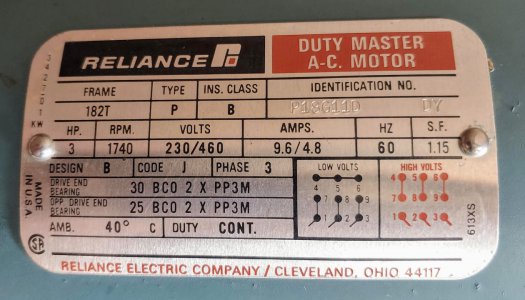
The motor base was larger than the one on the original motor. It fit the mounting plate but I had to drill new holes. I got it all mounted up but the shaft is 1.125" instead of the old motor's 0.875" so I had to bore out the motor pulley to fit. This eliminated the keyway in the pulley. I thought of making a new keyway but decided it wasn't worth the effort, this pulley will never see high torque or significant shock loads. I bought a longer 5/16-18 hex setscrew and turned the end down to 0.250" diameter to fit into the keyway on the motor without damaging it, should be just fine.
Then I mounted the VFD to the wall, not too low to avoid most chips. I wired a 20A 240V wall power outlet and made a cord to the manual starter and then to the VFD. I didn't have any more breaker spaces in my panel so I shared with the breaker for my MIG welder as I can't imagine ever using the mill and the welder at the same time. Many people have complained about the tiny screws on the VFD for connecting the power and the motor, and it's true! The spaces on the connecting strip only allow terminals up to 7mm wide. The opening in the plastic case is very close to the screw strip so there really isn't any room to hide the wires after you strip off some of the rubber jacket. I didn't want that look at all. Fortunately I had some large diameter shrink tubing and I was able to hide the wires outside of the case.
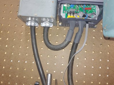
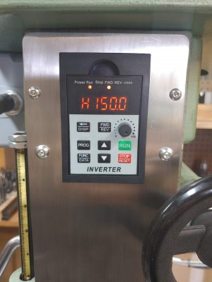
I actually chose the VFD I bought because it was listed as up to 12A when others said 10A, but mainly because it came with a 2 meter extension cable for the removable control panel. I didn't realize it before it arrived but it also included a plastic panel mounting bracket for the controller. I removed my mill's original power switch and pulley speed legend panel and made a new one out of stainless steel so the controller is right there on the front of the mill. I like it.
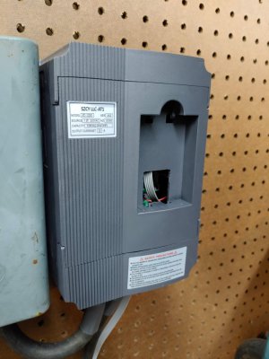
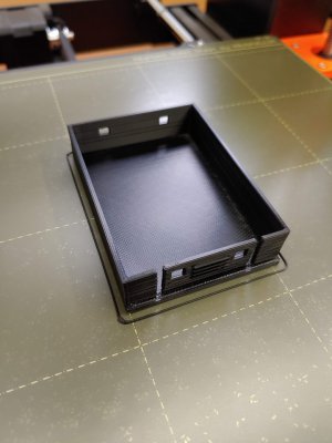
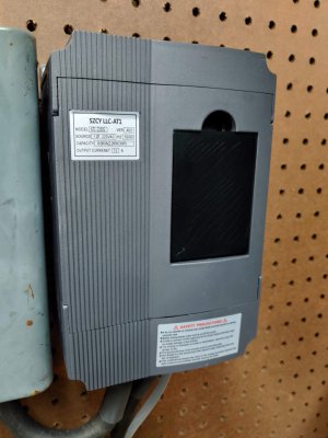
Removing the control panel left a hole in the front of the VFD. I had to relearn the tiny amount that I knew about using Fusion 360 and design a plug to 3D print to fill the hole. For anyone who doesn't already know, Fusion 360 is free to use for educational and hobbyist use. Search for "Fusion 360 free" (not the 30-day free trial). I really have to stumble through it, but then again, I'm old!
The VFD is able to output 3 phase power from 0 to 400 Hz and I am experimenting with speeds now. The motor will actually run below 10 Hz but not much torque. If you give it much more it is much stronger, it is after all a 3 HP motor with some power to give up and still have some reserve. I have currently set the upper speed frequency to 150 Hz which basically means the motor will run 2.5 times the speed on the name plate. Since its speed at 60 Hz is 1740 RPM I'm not worried about running it at 4445 (actual), that is not that far above normal speed for many motors. It sounds fine and runs smoothly. I read an opinion online by someone who should know that most motors can handle 5000 RPM without issue. Initially I have put the belts on for a spindle speed of a little over 500 RPM at 60 Hz. I just bought a laser tach so I can see what speeds I am actually getting. 10 Hz=87 RPM of the spindle, 150 Hz=1340 RPM. Initially I could stop the large spindle pulley with my hands at 10 Hz but one of the programming settings (P72) can add low speed torque and after setting it to 10 (range 0 to 100) I can't begin to stop the pulley now.
The VFD gives the motor a soft start and as the RPM would climb it would pass through some resonant speeds where the machine would rumble and vibrate. I suspected my old B-series V belts could be the cause so I replaced them with notched BX-series belts which are much more flexible and consistent width and all abnormal vibration is now gone. The belts came from offroadbelts.com and were super-cheap and only $3.99 total shipping. I underestimated how much effect there would be on the pulley spacing because the belts are slightly wider than the old 5/8" ones I had (the width was accurately stated on their site). When I contacted them about it, they sent me a longer belt for no charge when I had only paid them less than $15 including shipping for 3 belts! I offered to at least pay the second shipping charge but they said it wasn't necessary. Highly recommended by me.
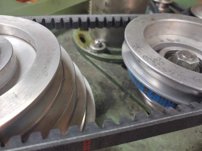
I think I'm going to like it. Total out of pocket for VFD and motor $160, a win in my book.
Some minor things:
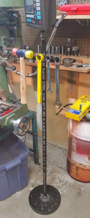
I had originally mounted the arm of my DRO display bracket to the head casting but it was slightly in the way. Then I moved it to mounting the arm to the bottom of the belt guard but it had a fair amount of vibration to it. Now I put a 3/4" floor flange on a flat barbell weight and mounted the display to the top of a pipe. This way I can move the display at will to the best spot I choose. I also made a little hanger rack to hold my hammer and commonly-used wrenches instead of always laying them on the milling table out of laziness.
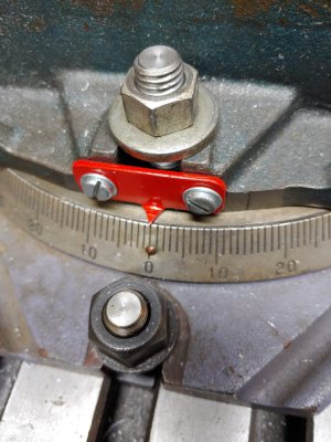
I bought a no-name swivel base for my vise from a friend. I found that the existing pivot pin was a sloppy loose fit in both the swivel base and the hole in the vise. I made a new pin that fits tightly in the base and is just a slip fit in the vise, so that should be better. I wanted to be able to use the degree scale on the base but my vise just had an open slot by the zero, so I faced off the ends of the slot and drilled and tapped holes and made a pointer to mount on there.
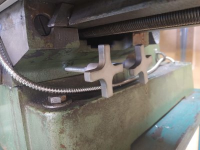
The locking screws for X and Y on my machine were just jokes, short and with just a little flat handles that flip on a pivot pin. I decided to make new locking handles that were larger and stuck out farther so they would be easier to grab and use. This is what I came up with and it's a great improvement I think.
Maybe you have seen my other post where I installed a DRO. I put the X scale on the back of the table because the front was in use for the stops and switch for the power feed. After a few times of the loss of Y travel interfering with what I was doing, I decided to move the scale to the front (now I just have the big vise to blame for limiting travel). I like to re-use existing holes where I can and that led me to mounting the read head too far to the right so that when I moved the table too far left it crunched the read head! I found a good deal on a new scale on Amazon but it was lost in shipment somehow. The seller replaced it and I mounted it up making sure to keep the read head out of the danger zone. I was then faced with the challenge of making the shield for the scale, the power feed stop switch, the locking knobs for the table, and the stops for the feed switch all co-exist in the space available.
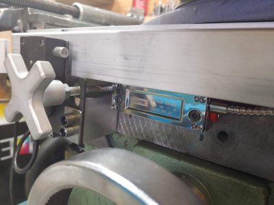
Then I had to address how to set stops for the power feed. I had to cut off part of the vertical face of the chip shield over the X scale to give some clearance over the locking knob screws. I made a couple of clamps to clamp onto that face. A friend gave me a 4" by 3/32" slitting saw but I had to make an arbor for it. I made two cuts in my clamp blocks with a thin blade in between that could flex over and provide the clamping action.
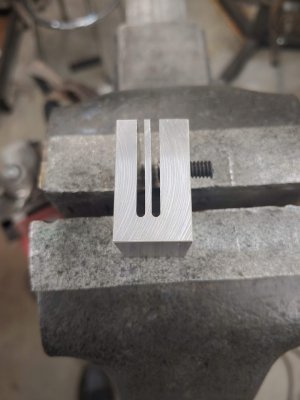
I drilled and tapped holes in the outer section, being careful to not hit the flexible blade. After partially power tapping the holes, I finished with a super-bottoming tap made by grinding off the whole point of a plug tap. I'm testing the clamp out here using some gasket material as a friction enhancer and to prevent excess scarring of the chip shield. Works great and all the knobs and switches and everything clear each other.
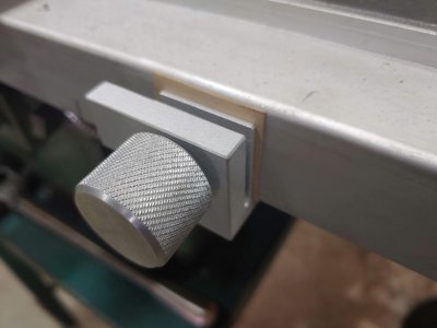
I guess that's all the news from here at the moment, now I just need to wait for something else to crop up that needs milling!
Rob
Power head lift!
First off, it is kind of awkward to have to reach and turn the crank handle to raise or lower the head, and seriously lacking in the cool factor. I decided I wanted to motorize that function so I started searching online for ideas. I toyed with the idea of adding a step to the motor pulley and using it to drive a lawnmower transmission I have that features an integral clutch, but that seemed too clunky and not cool. I looked at many gear motors on Amazon and eBay for ideas but nothing seemed right, too big, too small, too expensive, etc. I ended up going to a scrap metal yard near me where they save out some interesting items and sell them under the counter, no tax. I ran across a linear actuator that originally came from a Precor treadmill and it looked like it had possibilities. Here is what the one I bought looks like new:

I looked up the model and specs on my phone (MS-1000E, do a Google image search for this number and try "MSI linear actuator" and "MSI UC02" and "treadmill lift incline motor" and look for one exactly like this or a very similar configuration. Other ones could work but I know this one will). It said it could provide 1200 pounds of force at 6" per minute travel plus it's a line voltage AC motor that is reversible. This speed was sounding like it could be in the ballpark for what I wanted to do. I took it home and hooked up some power and it just hummed. I thought it was likely a bad capacitor (the black cylinder in the photo, it has a stud that screws into the casting). I had some trouble finding a replacement that was a match for the specs, size, and stud mounting and I didn't want to spend too much in case it was a dead end. I bought a physically larger one on Amazon with the proper capacity and hooked it up, it ran fine! The motor bearing sounded kind of rough, though.
I disassembled everything to see what I had (should have taken more photos, sorry.) The motor shaft had a helical pinion gear cut into it, driving a 2-step plastic gear which then drives a plastic gear that has a metal hub with a slot to drive a 5mm cross pin in a hole drilled through the output shaft. There were also a bunch of small gears that slowly turn a potentiometer to give some feedback as to the relative travel of the output jackscrew. I tossed all of these along with the pot as I had no use for that stuff. The rough bearing was on the gearbox end of the armature shaft where it also functioned as a thrust bearing, with circlips on the shaft on each side of the ball bearing. It took a fair amount of force to press the bearing out of the casting. I found that was due to the fact that the bore in the housing was only cast to size, not machined, and then swaged over the bearing race to contain it. The new bearing was not a very snug fit, so I managed to hold the housing in my 4-jaw chuck using only 3 jaws and taking a light cut. There was just enough depth to the casting to cut a groove for a 24mm internal retaining ring to contain the bearing. Now the motor ran very quietly. I wanted to make a new output shaft to replace the jackscrew but holding the assembly up to the mill it would have had to stick out too far for a good appearance. The inner end of the shaft went into a blind hole with a bushing and I thought I could have my new shaft come out that side, where there was currently a big boss in line with the jackscrew. I sawed off the boss and machined down the case until I reached the existing bushing hole:


Next, I made a new output shaft that would come out that side of the case. If anyone wants to duplicate what I did, make sure you leave enough length of the small diameter of the shaft so that it can slide in about 6mm extra to allow you to put the cross pin through the shaft on the opposite side of the gear hub and then it can move back over again. I oiled the bushings and greased the gears and put it all together. I made a sheet metal bracket to anchor the motor to the belt guard and mounted it up. I made the bends in the sheet metal less than 90 degrees so I could adjust the in-and-out distance by altering the angles. Then I could put the motor in position and mark where the screw heads were to position the holes to drill. I wired up some 6-conductor wire (fairly small gauge is fine for the low draw of this motor) in the end cover of the motor, bringing out ground, 3 motor wires and two capacitor wires. The motor wiring is simplicity itself: one common wire, one for forward, one for reverse. I found a plastic junction box at Lowes that was perfect, a completely blank box and cover so you can make the needed holes anywhere you like. I brought in a power lead and mounted my existing work light. In the cover I put the switch for the light and a SPDT center-off momentary toggle switch for the lift motor and there was room for the motor capacitor as well. Looks more official than a steel handy box and cover, I think.


Then came the moment of truth: I made sure the head locking nuts were loose and toggled the switch. Success! It moves the head up or down very quietly and with no fuss, about 3 seconds per inch of travel which seems very comfortable to me. It doesn't strain a bit, going up is about the same speed as going down. My total out of pocket: for the motor $5 (I already had a bearing), the box $15, the capacitor $9 and the momentary switch (less than $2 at Amazon, free shipping). I am very pleased, it definitely has the cool factor now!
Next: 3 phase motor and VFD
Changing speeds on my mill is a pain, especially since I have 3 belts instead of two as most of you do. As a result, usually the speed I use is whatever is already set up. I saw a guy on my local Craigslist offering 3-phase motors and VFDs for mills, lathes, etc. He wanted $420 for a setup, with not that strong of a motor (all new). That got me thinking and on Amazon I found several VFDs that were capable of up to 3HP and I ordered my choice. On my local OfferUp I found a 3HP Reliance 3 phase 1740 RPM motor coupled to a hydraulic gear pump that all looked nice in the photo. The problem was, it had been listed for 8 months! My biggest complaint about OfferUp is that things never expire! It worked in my favor this time, though, as he still had it. He lived about an hour away but was planning a trip my direction, so $60 and a short drive later I had a great motor. I thought maybe the pump would have some value but it turned out someone had crudely ground the shaft down a little bit, so bad luck there (the pump was otherwise perfect). It also came with a manual starter which I used as a power switch for the VFD.

The motor base was larger than the one on the original motor. It fit the mounting plate but I had to drill new holes. I got it all mounted up but the shaft is 1.125" instead of the old motor's 0.875" so I had to bore out the motor pulley to fit. This eliminated the keyway in the pulley. I thought of making a new keyway but decided it wasn't worth the effort, this pulley will never see high torque or significant shock loads. I bought a longer 5/16-18 hex setscrew and turned the end down to 0.250" diameter to fit into the keyway on the motor without damaging it, should be just fine.
Then I mounted the VFD to the wall, not too low to avoid most chips. I wired a 20A 240V wall power outlet and made a cord to the manual starter and then to the VFD. I didn't have any more breaker spaces in my panel so I shared with the breaker for my MIG welder as I can't imagine ever using the mill and the welder at the same time. Many people have complained about the tiny screws on the VFD for connecting the power and the motor, and it's true! The spaces on the connecting strip only allow terminals up to 7mm wide. The opening in the plastic case is very close to the screw strip so there really isn't any room to hide the wires after you strip off some of the rubber jacket. I didn't want that look at all. Fortunately I had some large diameter shrink tubing and I was able to hide the wires outside of the case.

I actually chose the VFD I bought because it was listed as up to 12A when others said 10A, but mainly because it came with a 2 meter extension cable for the removable control panel. I didn't realize it before it arrived but it also included a plastic panel mounting bracket for the controller. I removed my mill's original power switch and pulley speed legend panel and made a new one out of stainless steel so the controller is right there on the front of the mill. I like it.

Removing the control panel left a hole in the front of the VFD. I had to relearn the tiny amount that I knew about using Fusion 360 and design a plug to 3D print to fill the hole. For anyone who doesn't already know, Fusion 360 is free to use for educational and hobbyist use. Search for "Fusion 360 free" (not the 30-day free trial). I really have to stumble through it, but then again, I'm old!


The VFD is able to output 3 phase power from 0 to 400 Hz and I am experimenting with speeds now. The motor will actually run below 10 Hz but not much torque. If you give it much more it is much stronger, it is after all a 3 HP motor with some power to give up and still have some reserve. I have currently set the upper speed frequency to 150 Hz which basically means the motor will run 2.5 times the speed on the name plate. Since its speed at 60 Hz is 1740 RPM I'm not worried about running it at 4445 (actual), that is not that far above normal speed for many motors. It sounds fine and runs smoothly. I read an opinion online by someone who should know that most motors can handle 5000 RPM without issue. Initially I have put the belts on for a spindle speed of a little over 500 RPM at 60 Hz. I just bought a laser tach so I can see what speeds I am actually getting. 10 Hz=87 RPM of the spindle, 150 Hz=1340 RPM. Initially I could stop the large spindle pulley with my hands at 10 Hz but one of the programming settings (P72) can add low speed torque and after setting it to 10 (range 0 to 100) I can't begin to stop the pulley now.
The VFD gives the motor a soft start and as the RPM would climb it would pass through some resonant speeds where the machine would rumble and vibrate. I suspected my old B-series V belts could be the cause so I replaced them with notched BX-series belts which are much more flexible and consistent width and all abnormal vibration is now gone. The belts came from offroadbelts.com and were super-cheap and only $3.99 total shipping. I underestimated how much effect there would be on the pulley spacing because the belts are slightly wider than the old 5/8" ones I had (the width was accurately stated on their site). When I contacted them about it, they sent me a longer belt for no charge when I had only paid them less than $15 including shipping for 3 belts! I offered to at least pay the second shipping charge but they said it wasn't necessary. Highly recommended by me.

I think I'm going to like it. Total out of pocket for VFD and motor $160, a win in my book.
Some minor things:
I had originally mounted the arm of my DRO display bracket to the head casting but it was slightly in the way. Then I moved it to mounting the arm to the bottom of the belt guard but it had a fair amount of vibration to it. Now I put a 3/4" floor flange on a flat barbell weight and mounted the display to the top of a pipe. This way I can move the display at will to the best spot I choose. I also made a little hanger rack to hold my hammer and commonly-used wrenches instead of always laying them on the milling table out of laziness.

I bought a no-name swivel base for my vise from a friend. I found that the existing pivot pin was a sloppy loose fit in both the swivel base and the hole in the vise. I made a new pin that fits tightly in the base and is just a slip fit in the vise, so that should be better. I wanted to be able to use the degree scale on the base but my vise just had an open slot by the zero, so I faced off the ends of the slot and drilled and tapped holes and made a pointer to mount on there.

The locking screws for X and Y on my machine were just jokes, short and with just a little flat handles that flip on a pivot pin. I decided to make new locking handles that were larger and stuck out farther so they would be easier to grab and use. This is what I came up with and it's a great improvement I think.

Maybe you have seen my other post where I installed a DRO. I put the X scale on the back of the table because the front was in use for the stops and switch for the power feed. After a few times of the loss of Y travel interfering with what I was doing, I decided to move the scale to the front (now I just have the big vise to blame for limiting travel). I like to re-use existing holes where I can and that led me to mounting the read head too far to the right so that when I moved the table too far left it crunched the read head! I found a good deal on a new scale on Amazon but it was lost in shipment somehow. The seller replaced it and I mounted it up making sure to keep the read head out of the danger zone. I was then faced with the challenge of making the shield for the scale, the power feed stop switch, the locking knobs for the table, and the stops for the feed switch all co-exist in the space available.

Then I had to address how to set stops for the power feed. I had to cut off part of the vertical face of the chip shield over the X scale to give some clearance over the locking knob screws. I made a couple of clamps to clamp onto that face. A friend gave me a 4" by 3/32" slitting saw but I had to make an arbor for it. I made two cuts in my clamp blocks with a thin blade in between that could flex over and provide the clamping action.

I drilled and tapped holes in the outer section, being careful to not hit the flexible blade. After partially power tapping the holes, I finished with a super-bottoming tap made by grinding off the whole point of a plug tap. I'm testing the clamp out here using some gasket material as a friction enhancer and to prevent excess scarring of the chip shield. Works great and all the knobs and switches and everything clear each other.

I guess that's all the news from here at the moment, now I just need to wait for something else to crop up that needs milling!
Rob
Last edited:


