Rotary Phase Converter data analysis

rabler

Addlepated tinkerer
H-M Lifetime Diamond Member
Joined
Feb 25, 2021
Messages
3,130
I figured I'd start a new thread to separate this from my rotary table controller thread. It might be of interest to some others here as it evolves over the next few months.

Not too long ago I purchased a "project" VMC, one that will need plenty of TLC. It draws something like 60amps @ 240V three phase. That is not a small phase converter. My current phase converter uses a 20HP idler. I built a new shop in the last year, so I ran wire suitable for up to 125A (at single phase 240V) to the phase converter. So I should be able to expand my RPC by adding an idler.

I equipped my phase converter with voltage and amperage displays. But unless you are standing in front of the panel staring at the displays, they are of limited value. Certainly don't need to be trying to turn something on the big lathe while staring at the RPC. (My <5HP machines use VFDs, so only the big things require the RPC).

So in parallel with another microcontroller project, I've used a Raspberry Pi Pico and am working on a three phase logging tool. Using a 6 channel differential A/D converter and some isolation transformers I'm able to capture voltage and current on all three legs sampled at 1.041 ms (16 samples/cycle of 60Hz). Well, so far I've used a cheap furnace transformer as a bench test. Anyway, roughly every 1/2 second I'm getting a dump of voltage/current, phase and noise for all 6 channels. Goal is to use a Pico W to send the data wirelessly to a Raspbery Pi 4 B to capture along with a real-time timestamp. A simple web server on the RPI 4B can give stats, history, etc, etc. and the raw data will be logged for analysis. (I also plan on a mode where the raw samples can be dumped).

Ultimately I'm hoping to implement a "smart" RPC, and be able to switch in/out some balance caps to keep the voltage near ideal. Yeah, American Rotary already implements something like that in their higher end series, but this is a DIY project.

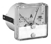
Here's an obligatory picture of my furnace transformer pretending to be a RPC. Note the potentiometer to allow me to vary the output a bit.

0D5DBAD0-8794-43C5-A7BE-3AE54CD6ED00.jpeg

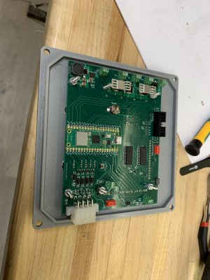
The board I'm working on. The blue cable is going off to my stepper (see the rotary table thread). The ribbon cable (bottom right of first pic) goes to a rotary encoder "knob" for user input. The top right connector with a couple of test leads/wires is the A/D inputs.
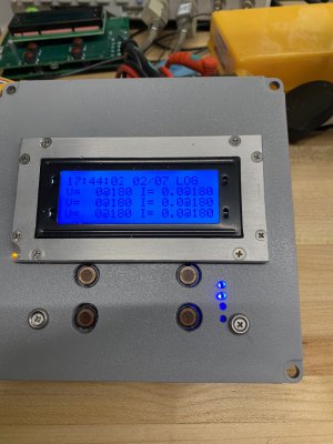
BB117A2E-5334-4BDB-8444-9D7BFDFA6F68.jpeg

Front face of same:
2EE706FB-75FE-4128-8D5A-98E72DEBBF78.jpeg
 
Last edited:
Okay, my first thought was to use analog peak gauges on your existing setup, but what you're coming up with is so far beyond that!

APLTONE01221_WB_274_PE_001.jpg

I'm just trying to mount my 20 hp RPC panel close enough to the lathe that I can keep an eye on it... but now I might need to re-think it...
LOL, yeah. I'm going off the deep end. I do have a Fluke clamp ammeter, and my lathe does have a load meter based off a current transformer on one of the legs.

I'm hoping to get a better understanding of RPC voltage/current/phase dynamics this way.
 
I have never tried it but capacitors can be used on existing motors.I have some literature on the subject somewhere. But the world of electracraft is progressing to the , -(Quantum World .) energy from the other side......
 
Got the WIFI sending of the results to the server working. Just using netcat (nc) on a Raspberry PI 4b board for now to receive the results and append it to a file, but any linux box would work just as well. Simple text file, comma separated values.

My circuit board includes a battery backed real time clock, so next step is to set that up so that the logging includes accurate date/time stamps even accross power cycle/reboots.
 
Setting up to do some calibration. The wires to the connector along the top, just right of center, are my inputs. V1 and V2 are jumpered together. Logically that would mean V1 and V2 should read the same.
IMG_4954.JPG
Since it is a single A/D converter that is multiplexing across 6 channels, there is some phase shift between channels when sampling identical signals. Similarly, the tolerance on the RC components in front of the AD converter can result in minor offsets in phase and magnitude even when the same signal goes into both channels. I've built in some calibration routines to help, but are not using those in this picture. I'm still working with the little thermostat transformer. I'll want to build a box for this before connecting 240VAC, and that will be through current sense and step-down transformers.

While my primary focus is on monitoring my RPC output, it occurred to me that I really should have included 5 channels of current sense, that way I could completely characterize what is going on in the RPC, getting the input current as well as the output current. Kirchoff's law would allow calculating the current into the idler (i6, i7 in the image) if i1 and i2 are measured. That would allow calculating things like how much power was u$ed turning the idler. I'll add this as a feature IF I make another revision on the circuit board.

IMG_E4952.JPG
 
Not really a whole lot of difference in the appearance here. Spent quite a bit of time getting the WIFI features cleaned up and working well. It now powers up logging magnitude and phase roughly every 1/2 second over the network for every channel. I also log a few technical statistics for each channel, DC offset, and total noise. DC offset should be zero from a transformer, but I have to offset bias the signal before A2D sampling to a positive voltage (+2.048 volts to 0 volts). The noise is just the sum of the square of the FFT bins other than DC or 60Hz. The noise figure gives a good indication of lots of potential problems, true noise on the power signal, but also saturating the A2D converter, or timing errors (including clock drift) that can mess up sampling. I'm stabilizing the clock period by a using a small delta on the sampling period which is dynamically adjusted based on the phase of the incoming single phase 240V.

I did add a couple of features where it can be commanded over the network to dump the actual samples (every 1.047 milliseconds) of every channel. (Channels are V1, V2, V3, I1, I2, I3). Also have it set up so that the voltage and current calculations have a magnitude and phase calibration feature that can be adjusted over the network. This allows for variation in the isolation transformers. I'm using a little I2C chip with a time-of-day clock and a few bytes of SRAM to store the calibration table. That I2C chip has a little button cell battery so it keeps those calibration entries even if powered off.


Close comparison of this picture will reveal a few key differences. Biggest one is that this is a new spin on the board. Took several days to get that populated and debugged. The two blue LEDs indicate network logging activity, showing that the network is up. I did include the TFT interface on this spin, but I'm going to go ahead with the LCD character display on this unit. Working in the TFT will take a fair amount of coding, starting with porting the Adafruit/Arduino library into the Raspberry Pi SDK, which I'm using rather than the Arduino IDE. I'm targetting that for the rotary table controller.

Anyway, time to make up a box for this and put into live testing. It is sized to easily fit into a standard electrical PVC 6"x6"x4" box. I just need to mill out the cover for the LCD and a few light pipes for the LEDs. Seems a shame not to use the 4 pushbuttons for something, but I could add features endlessly.
IMG_4958.JPG
 
Last edited:
A few pics, including a machining shot since it is a machinist forum:

It's a 0.250" thick piece of PVC for the top but it was dicey milling it in the vice, it wanted to pick up. Used a 3/16" aluminum 2 flute end mill turning at 500 rpm, no coolant, slow feed. Ended up tabbing the large cutout for the display, I started thinking I'd cut it out all around but it kept bowing up. If I had to do it again I'd clamp it down to a sacrifical surface.

Tomorrow I'll work on a bezel around the display. The buttons would have recessed too far if I tried to flush the PVC to the LCD frame. I ordered a small piece of 1/8" acrylic rod to make some light pipes for the LEDs, they'll get pressed into the 5 small holes. The other two intermediate sized holes are part of the mounting).


IMG_4960.JPGIMG_4963.JPG
IMG_4959.JPG
 
Prototype going together. Got the bezel made. I didn't leave enough room around the LCD so the top two buttons and the yellow power on LED are not a great fit. But those are basically cosmetic. Later this week I can start wiring it into the RPC. I'm also assembling the electronics for another one so I have a bench version.

Debating the merits of writing a fancy program on the receiving end linux box. For now it is just logging to a text file via the linux netcat (nc) program. I can pull data out of that with AWK and play in Excel or LibreOffice easily enough if I want to do anything technical. But it wouldn't be that hard to slap something together in PHP or python and apache to make it something I could click through on the web. Something like rrdtool to put out graphs would be fancy. Just not sure how much time I'll put into that end.
 

Attachments

  • IMG_4967.JPG
    IMG_4967.JPG
    263.8 KB · Views: 8
  • IMG_4969.JPG
    IMG_4969.JPG
    300.5 KB · Views: 9
Back
Top