- Joined
- Feb 25, 2021
- Messages
- 3,130
Having fun working on this. Which is a good distraction as the holidays included a broken rib, a damaged pickup truck, and a furnace failure on Christmas day during the tail end of that arctic blast. Almost sounds like a bad country western song.
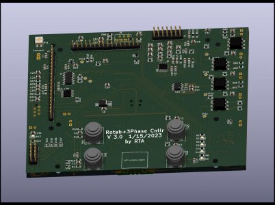
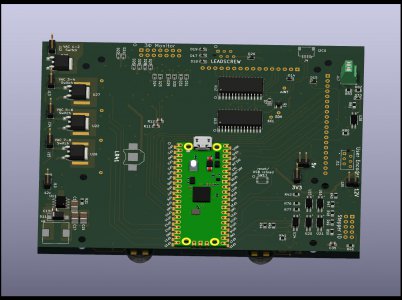
I'm building the controller for this as a swiss army knife. Meaning I didn't quite go as far as including the kitchen sink. But I did stuff as much onto the board as I could interface into the $5 Raspberry Pi Pico RP2040 that I'm using as a microcontroller.
My circuit board has an external I2C based A2D converter with 12 channels, (6 channels if set up in differential mode), four 4A triacs rated for 400V, outputs for a stepper with a PWM input for the Clearpath SDSK line of torque feedback, 4x20 character LCD interface, SPI interface for a 320x480 TFT display with a resistive touchscreen controller, inputs for a user driven rotary encoder knob, inputs for a leadscrew encoder, and a qwik I2C interface plug for expansion gadgets, four buttons for user input, and a few LEDs, all with supporting circuitry, optical isolation for the external inputs, etc. Maybe I did get the kitchen sink in there somewhere, I should double check the schematic.
So the goal for the "rotary table" controller is to also include input from a leadscrew encoder so that it can act as a helical cutter on a mill, i.e., take the place of a leadscrew attached dividing head. There is a name for those that escapes me at the moment. I've got the menus set up for the basic rotary table operation, and an LED flashing for stepper pulses, waiting for a cable from Teknics for the clearpath stepper. So when those arrive I'll start building the stepper mechanical interface for the table. (Machining work!)
Given the sore ribcage, I've been playing with the other side of the board. A/D converter. My goal here is to sample the voltage and current on all three legs of the RPC. I can put a copy of the board in an enclosed PVC electrical box with conduit to the RPC panel, and capture the performance of the RPC. Transmit aggregate results over wifi to a linux box (probably a Raspberry PI but TBD) for logging. That will keep all the wires connected to the RPC safely enclosed in electrical rated boxes. For development I'm simulating the RPC with a 120VAC -> 24VAC output home thermostat transformer I happened to have lying around.
I'm sampling all 6 input channels at 960 samples / second/channel. So 480Hz nyquist frequency, or 16 samples per cycle of 60Hz, or 1.041667 ms sampling period. The external A/D converter I'm using nicely samples all 6 inputs in a burst and sends 12 bytes (10 bits per sample).
I'm recording 512 samples per channel across all 6 channels. That takes 512*1.042ms. A little more than 1/2 a second. One core of the RP2040 is FFT'ing all 6 channels in 94ms. That's using 16 bit integer FFTs. Floating point FFTs took about 295 ms, I may go back to that. Anyway, FFTing the results gives me an easy way to extract relative phase and amplitude, plus a measure of noise power across the other frequency bins. I haven't implemented interleaving the FFTs with the sampling but that will be easy as the sampling is already interrupt driven, just need a bit of coordination and a second input buffer so I can fill one buffer while transforming the other. Have to implement the wifi interface first though, as printing all that data to the screen is kind of pointless. Question of whether I implement the WIFI on the FFT/sampling core or the other core, I need to delve into the interrupt priority of the wifi vs. the timer I'm using for the A/D sampling as I wouldn't want the A/D sampling period trashed by wifi I/O.
Goal is eventually to not only analyze and log the RPC performance, but eventually use the triacs to switch in load balancing capacitors (via a contactor) as needed to adjust for significant load changes. At least that is the idea.
My interface cable for the stepper should arrive any day. Out of the electronics world for a bit and back to machining to build the rotary table mount.
Last edited:


 Regarding the elex work,
