Rotary Table Conversion

Chris S

Registered
Registered
Joined
Sep 11, 2014
Messages
6
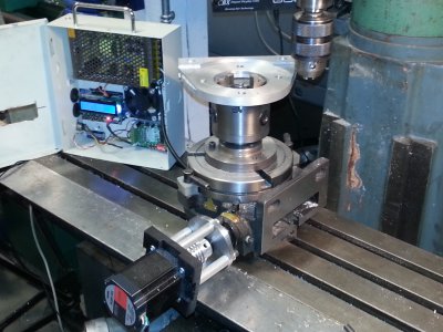
Just wanted to thank Gary Liming for his article in Digital Machinist for an Arduino controlled rotary indexer. I completed the conversion to my rotary table with a stepper motor and it works great. No more index plates no more counting turns. It works awesome as well for radiusing parts in the continuous state. You really don't need to be an electronics whiz to build this and there are a ton of motor mounting ideas on the web. The download is easy for the software Gary put together which is the real time saver.

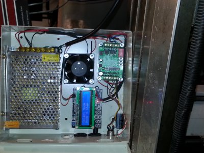
I added a couple of pictures as requested. Going forward I want to cast a better motor mount and set it up so I dont have to block the rotary tabe up from the mill table to clear the motor. The fan is unneccesary at the moment but I hope to finish the cover with external switches at a later date.
:))

20141106_060835.jpg 20141106_060908.jpg
 
Last edited:
Looks good. Just ordered the parts to do the same. Just waiting for the slow boat to bring the parts. Looks like you used a different stepper driver than Gary did? I see a large capacitor and wonder why you used it?
Thanks
 
My bad... tried to edit my post but too late. You did use the same driver for the motor and his schematic shows a capacitor. Still not sure why a capacitor is needed.
 
Very clean build! I like it! What's the oz/in rating of the stepper you used?

Does the table have enough backlash that you need to lock it down when cutting, or can you safely cut on a rotating workpiece?


As for the capacitor -

If the capacitor is across + and - for the DC supply that drives everything, it's for ensuring the DC is smooth and ripple free. Non-filtered DC wreaks havoc on digital circuits, and even a little bit of smoothing is better than none. If the capacitor isn't big enough (in microfarads, uF), it can't supply enough current to keep the voltage up during the low points in the ripple from the rectifier. The voltage will fall, and integrated circuits can do odd, random, and frustrating things.

One item I usually do when putting a filter capacitor on a DC power supply, is make sure it's located upstream (before) the fuse. Otherwise, if a circuit gets shorted out, the capacitor is free to dump all it's energy into the short, and the fuse will pop when the drain on the rectifier gets too high. If the capacitor is placed before the fuse, if the circuit gets shorted, the current from the capacitor will blow the fuse in very short order.
 
Thanks Guy's. I cut the radius on the bracket in the picture without using the table locks but I can't say they were heavy cuts. 10 - 20 thou and it worked fine. The motor is likely larger than the one Gary used but I had fished it out of the electronic recycling bin at my old apartment one morning and it was like new. I looked the spec up on it way back and I think it's in the 368 0z- in range? As for the capacitor you answered the question for smoothing the voltage out. Size wise it matched the uf Gary used and it was in my scrap box. I'm sure one that's smaller would work as well if the uf rating is close.

I'm currently using the Ralph Water's PWM controller software for a tach on the mill from the Summer 2013 Digital Machinist and I will post the results when I am done.


Have a great rest of your day everyone and thanks for the feedback
 
Chris,

Which issue of Digital Machinist has the article in for the Arduino contolled rotary indexer? That's definitely something I would like to add to my shop.

Thanks,

-Ron
 
Back
Top