- Joined
- Nov 10, 2013
- Messages
- 837
There is more than one way to set equipment up for use and we all have our favorites. The rotary table is no exception. Hopefully all of the setup ideas can be lumped into a single thread so none of them will get lost in the fray.
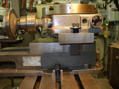
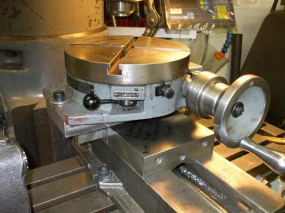
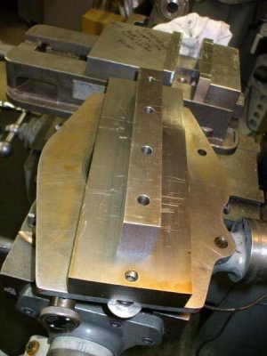
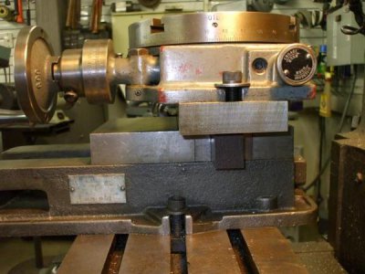
Rotary tables of any size are heavy and we all tend to put off setting them up because of the hassle of clearing the mill table (removing the vise) and getting the rotary table mounted and trammed. In my case setting the vise back up and tramming it in afterwards was just as much hassle so I figured out another way. I had a bar of rusty 4" x 1.5" S7 standing in the corner so I decided to make a vise mount for my 9" Troyke table. I milled the rust scale off and ground the sides square.
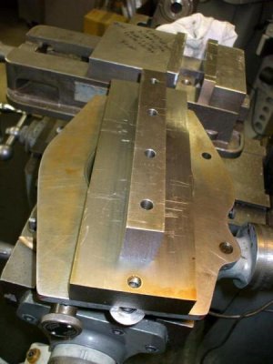
The mount drops into my vise and closing the jaws locks it in place with the top level and square to the mill.
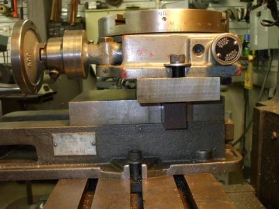
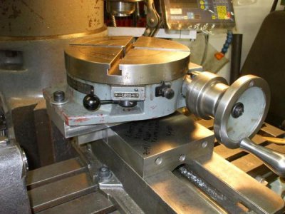
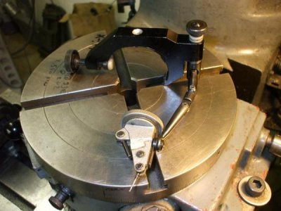
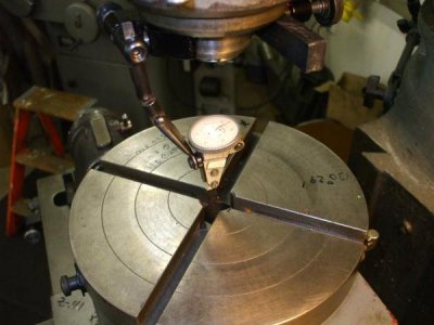
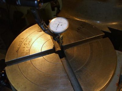
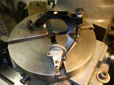
For the last 34 years I've been using an indicol with a top dial indicator mounted to it for most of my setup work. This setup makes it as easy to tram surfaces as it is to tram hole locations. You can also use it to locate edges precisely and measure radius sizes and locations without changing the indicator. Indicol is a brand name and there are generic indicator holders available that do exactly the same thing for way less money.
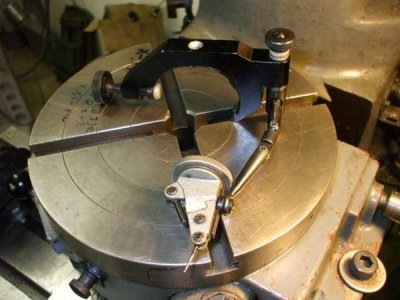
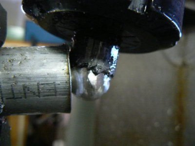
The indicol mounts to the mill spindle to rotate with the spindle. I use a 3" long chunk of scrap plastic between the clamp screw and the spindle to use as a handle for rotating the spindle but if I'm doing something precise I use the belts from the drive motor to rotate the spindle by hand and don't worry about influencing the indicator by accidentally moving the clamp on the spindle. There are a lot of moveable joints in the setup that allow you to precisely position the indicator. The next step is to move these around and get the indicator positioned until the ball on the indicator tip stays still as the spindle is rotated. in other words, the ball on the indicator tip becomes the center of the universe and everything else spins around it. Once centered, use the XY table handles to eyeball the indicator ball to the center of the hole you want to tram.
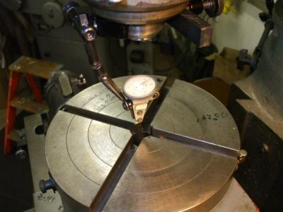
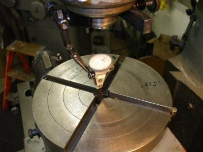
I always turn the rotary table so the contact points of the center hole are aligned with the table axis then push the stem of the indicol forward so the indicator tip touches the side of the hole to be trammed and set a zero on the indicator.
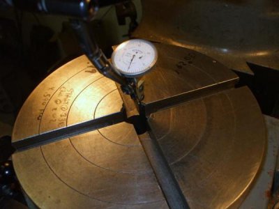
From there it's just a matter of rotating the spindle and positioning the table so that the indicator reads zero on all contact surfaces.
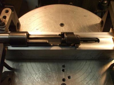
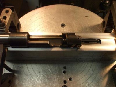
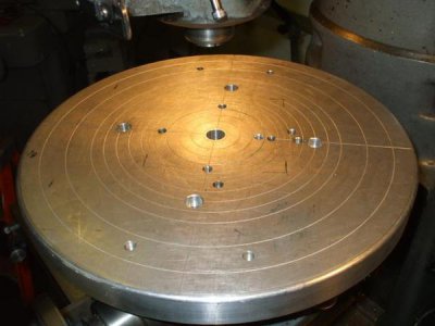
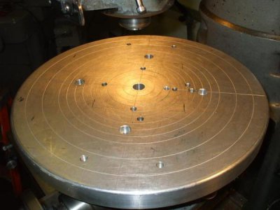
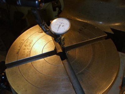
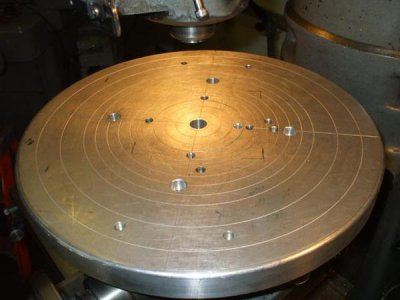
My last rotary table trick is just a plate I made for the top. I had a project where I needed to cut about a 4.5" radius on a large plate. The plate was too large to bolt to my 9" table so I bought some 1" thick aluminum, mounted it to the table and machined the outside diameter of the plate to 16". I used a small centerdrill to machine the setup lines in the top for future use. The drawback to the top plate is I have to drill and tap holes for clamps. The good thing is that I can use it for dedicated setups by only drilling and tapping holes one time.
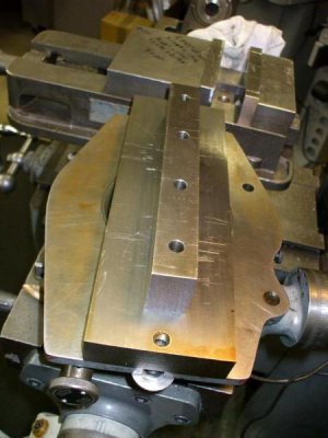
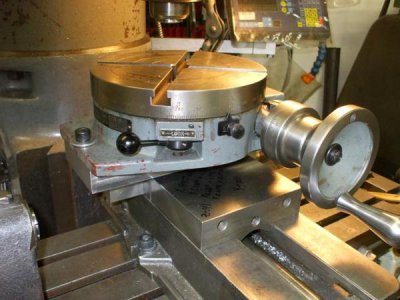
Rotary tables of any size are heavy and we all tend to put off setting them up because of the hassle of clearing the mill table (removing the vise) and getting the rotary table mounted and trammed. In my case setting the vise back up and tramming it in afterwards was just as much hassle so I figured out another way. I had a bar of rusty 4" x 1.5" S7 standing in the corner so I decided to make a vise mount for my 9" Troyke table. I milled the rust scale off and ground the sides square.

The mount drops into my vise and closing the jaws locks it in place with the top level and square to the mill.


For the last 34 years I've been using an indicol with a top dial indicator mounted to it for most of my setup work. This setup makes it as easy to tram surfaces as it is to tram hole locations. You can also use it to locate edges precisely and measure radius sizes and locations without changing the indicator. Indicol is a brand name and there are generic indicator holders available that do exactly the same thing for way less money.

The indicol mounts to the mill spindle to rotate with the spindle. I use a 3" long chunk of scrap plastic between the clamp screw and the spindle to use as a handle for rotating the spindle but if I'm doing something precise I use the belts from the drive motor to rotate the spindle by hand and don't worry about influencing the indicator by accidentally moving the clamp on the spindle. There are a lot of moveable joints in the setup that allow you to precisely position the indicator. The next step is to move these around and get the indicator positioned until the ball on the indicator tip stays still as the spindle is rotated. in other words, the ball on the indicator tip becomes the center of the universe and everything else spins around it. Once centered, use the XY table handles to eyeball the indicator ball to the center of the hole you want to tram.

I always turn the rotary table so the contact points of the center hole are aligned with the table axis then push the stem of the indicol forward so the indicator tip touches the side of the hole to be trammed and set a zero on the indicator.

From there it's just a matter of rotating the spindle and positioning the table so that the indicator reads zero on all contact surfaces.
My last rotary table trick is just a plate I made for the top. I had a project where I needed to cut about a 4.5" radius on a large plate. The plate was too large to bolt to my 9" table so I bought some 1" thick aluminum, mounted it to the table and machined the outside diameter of the plate to 16". I used a small centerdrill to machine the setup lines in the top for future use. The drawback to the top plate is I have to drill and tap holes for clamps. The good thing is that I can use it for dedicated setups by only drilling and tapping holes one time.


