Rotary Table Workaround

benster

Registered
Registered
Joined
Mar 14, 2016
Messages
57
Hello all.

I'm trying to cut three slots in a cross section of pipe to make a steady rest. The pipe is 8" OD and the closest thing I have to a rotary table is a dividing head for Taig sized chucks. Is there a trick or technique to aid me in locating the three slots? I have a DRO setup and was thinking I could locate center then use coordinates for six pins equally spaced around the diameter. I could then use these pins to hold a bar and indicate off the bar to get my y axis parallel with each slot. I can then find center and mill the slot.

Anyone have any suggestions? Worst case I can pester the guys at work and have them put in on the CNC. I'd like to do it myself though. I've attached a drawing of what I'm thinking.
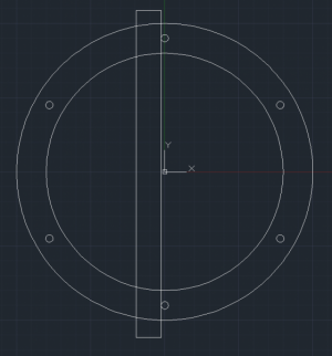
Capture.PNG
 
A steady rest is not a precision job. You can take dividers, set them to the radius of the circle, and then, starting at any point around the circle, mark off increments with the dividers. You will come out even with 6 divisions. Use every second one, and you are done with the layout. Machine the slots centered on those three locations.
 
Setup your ring on the table against 2 flat bars set up as a V. Clamp the ring down against the V. Pick up center and then drill your 3 holes starting with hole at top. Go back to first hole and mill your slot. Then go back to readings for the hole. Using a pin that fits the hole rotate the ring against the V until the pin drops into the next hole. Mill your slot and then do same thing for 3rd hole.
 
the radius is your between hole measurement...easy
 
A steady rest is not a precision job. You can take dividers, set them to the radius of the circle, and then, starting at any point around the circle, mark off increments with the dividers. You will come out even with 6 divisions. Use every second one, and you are done with the layout. Machine the slots centered on those three locations.

If I may, Bob is essentially saying drill three holes 120° apart.
 
As mentioned above a steady must be adjustable by design, if you are off by 10 degrees this will not effect how it works.
 
If I may, Bob is essentially saying drill three holes 120° apart.
I was just saying how to lay it out, fairly accurately and plenty fast. There are lots of ways to machine what you want, and the OP was not too clear about the details of the design...

Edit: my actual idea was to lay it out on the cut end of the tube with dividers, then cut the slots any way that works.
 
I went lazy when I made mine. Chucked it in the 3 jaw and marked it up.
 
Considering the large diameter of the pipe, run a piece of masking tape around the pipe, as close to straight as possible. Cut the finishing end square across, then mark where that meets the start of the tape. Some overlap is good. Carefully remove the tape and lay it out on a flat table. Measure from the end to the mark, then divide that distance into three. Transfer the tape back to the pipe and mark for your slots.
 
Setup your ring on the table against 2 flat bars set up as a V. Clamp the ring down against the V. Pick up center and then drill your 3 holes starting with hole at top. Go back to first hole and mill your slot. Then go back to readings for the hole. Using a pin that fits the hole rotate the ring against the V until the pin drops into the next hole. Mill your slot and then do same thing for 3rd hole.

Exactly
 
Back
Top