Rotating parts in a V-block

durableoreo

H-M Supporter - Gold Member
H-M Supporter Gold Member
Joined
May 3, 2020
Messages
229
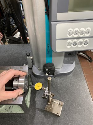
Is there a better way to get a part (in a V-block) parallel to the surface plate?

I'm measuring the flats in a socket. Unfortunately, it must be quite level to get an accurate reading. I've been sweeping the flat with an indicator, then going back to the TesaHite to get the measurement. Back and forth. Same for the drive end, but it's a different height. I'm constantly adjusting the indicator to sweep the flat. I have quite a few of these to do. Is there a better way to do this?
 

Attachments

  • socket_in_vblock.jpeg
    socket_in_vblock.jpeg
    280.6 KB · Views: 84
I take it those sockets aren't going to be taking lugnuts on/off.
I'll also take it you have no CMM to work with. And customer has specified accuracy of fitment to .001" or some such?
 
What features are you measuring: location of the square hole relative to the round OD, if the square is actually 90.00 degrees square, the size of the square hole, . . . .? A square hole can be a bit tricky to measure accurately. One way to measure a square (or rectangular) hole is with nice square blocks + feeler gauges. Some gauge blocks would be nice, I don’t have any gauge blocks so make do with parallels, 123 blocks, or grind a piece of scrap metal - what ever is close to make a stack and I can get a micrometer on.

If it is just a tolerance that you are trying to hit, and the actual number doesn’t matter - turn a scrap of bar with a go no-go step (very quick to check your parts (only works on square holes and won’t catch if one dimension is good and the other is over.

If you have quite a few, mill/grind some rectangular bar stock for go no-go gauging ( put it in one way, flip it the other - if they are both in range, good to go).
 
Am I missing something? Vernier/Dial/Digital caliper, measure between the flats at each end top-to-bottom & side-to-side?

Or are you trying to get the surface parallel to the surface plate so you can check back-to back? If so, mount in a rotary table chuck so you can rotate it to get parallel then check in & out. It doesn't need to be perfectly concentric, just square to the surface you are checking, so you could even clamp the Vee block to the rotary table, then clamp the part to the Vee block.
 
@Chipper5783 Trying to measure the size of the square hole. A gage block stack and a few feeler gages might be a quick way to measure.

@Bone Head I don't have a CMM, unfortunately. The electronic height gage is a poor man's 1-dimensional CMM. It is attached to a computer. I have a text file on the computer that prompts me so I know what to measure. It records the results, and shows whether a measurement is within tolerance. The tolerances on the drawing vary but some are +/-0.001

@ChazzC Calipers are OK in theory but you need to get them perpendicular, too. Even Mitutoyo calipers are +/-0.001 for this range. Also, I've had the internal jaws catch on the texture, making it hard to get a good measurement. Even if hand-held calipers was reliable, I'd have to record it by hand, which I'm trying to avoid.
 
Could you clamp a good flat block against the surface of interest, and use an adjustable parallel to
fill the surface plate/block space?
 
Why wouldn’t or couldn’t you clamp a parallel, ( that fits inside the square hole with clearance), on top of some other equal height parallels to enable hanging the part on the parallel and then indicate / height check the lower surface to verify parallel with upper flat and size? Then remove and rotate part 90 degrees to check the other two flats orientation and size while hanging on the parallel????
 
so I was thinking of using an adjustable parallel and a regular parallel. Use the adjustable to set the parallel level (not important that it be exact), and lay a parallel in the socket, and across to the adj. parallel, press down on the spanning parallel to set. that should get you quite close immediately if you have a quality adj parallel.
 
Back
Top