Sanco Mill electrical issue with a transformer???

Based on the wiring diagram, those are the output terminals on the top, there should be two additional terminals/wires that are the input (220V). With the plug and power disconnected you should be able to check the resistance of the primary side of the transformer, it should read a few ohms, but not 0 which would be shorted.You will see continuity on between 0 and the other terminals on the top as they are all taps on the same winding, the wiring to them appears correct based on the schematic.. If you are blowing the line fuse on power up with all the controls off, then it might suggest a short somewhere. You could rule out an issue with the transformer by disconnecting the input power to it and powering up the unit. If you are blowing the main power fuses, unlikely to be the transformer because it cannot draw that level of current.
 
From the labeling on the transformer I too suspect it is an autotransformer.

While hard to follow due to size and lighting, from that circuit diagram, it looks to me like contactor MS5 is crowbaring across all of the power lines. Perhaps some safety feature or emergency stop? If so I'd want to eliminate that as the source of the problem
 
Last edited:
Good that you found some diagrams, I think there's a chance we can fix the fuse blow issue
The transformer does not seem to match the diagrams, we may have to do some tests on it to see what type it is
My guess it has been kludged up as an autotransformer to step down from 220 to 110
 
Last edited:
Looks oddball, let me GUESS...

First, check the different motors to see if they are multi-voltage.

Looks like ONE control for international use, the control transformer LOOKS backwards but me thinks it is just a label to direct you on where to connect output depending on your local voltage.

There is likely some contractors someplace, the panel buttons control the contractors.

Contractors powered by the "control" transformer and they control or switch power to the specific motor or device.

This is 3 phase so will assume you have RPC.

A SPC only works if the real line power are on the 2 wires connected to the transformer.

Should be 4 wires connected to transformer, 2 in and 2 out.

Locate the ones connected to input, easy with ohm meter or just hand trace.

Disconnect ONE of them and try again.

If it still blows a fuse you have pinched wire maybe.

For tracing this you may just need to. Place ohm meter across the power connection and carefully lift wires one at a time until it changes.

The labeling on transformer is odd.

Too many things connected.

Good luck

Sent from my SM-G781V using Tapatalk
 
An auto-transformer would not show as two separate windings, but who knows how they draw the schematic. If there are no other connections to the transformer than that could be true. It indicates that they feed the control coils, so if you follow the yellow wires to their destination, then it might be that there is a jumper/selector which is used based on the feed voltage to the machine, as it came in both a 220 and 440V version (and possibly other voltages). The Control switches show they are connected to R and T, this could be direct power or from the transformer. You need to follow the transformer wires to see where they connect. I see two smaller glass fuses at the top of the cabinet which I assume are protecting the transformer, you should be able to remove the fuse and ohm out the other end of the connections as they should be 0 ohm. Without mapping it out you can't determine where there is an overload/short. It is also possible that the fuses are wrong type, sometimes on the input side of a transformer one will use a slow-blow because of the turn-on inrush. There are manuals on this model, not cheap and not sure it will show you much more electrically, but may be worth it in the long run. Can also call Jet and see if they have one for their version.

There is a second part to the diagram which is the control panel description, the right side corresponds to M1-8 which refers to the perspective contactor, MS1-MS8. NS1/MS2 is table knee motor (M1) up/down, these are interlocked and also have limit switches, MS3 is the ventricle spindle motor (M2) which appears to have momentary buttons for on/off for FOR/REV with latching contactors interlocked between contactors, MS4/MS5 I assme is reverse and 2nd contactor might be for the dual speed motor. MS6/MS7 is a single switch assume self centering for the the table feed motor (M3) right/left, interlocked and with limit switches, MS8 is the horizontal motor (M5), forward only. Coolant pump motor is M4. FB1 is the stop button for the vertical and horizontal motors. The ON may be the power to the control circuit, would pop off the panel and see if the yellow wire supply power to the machine controls. It may also be that there is a main power contactor, but not shown on the schematic.

Interesting that there appears that ther are no thermal overload relays attached to the contactors or additional fusing protecting against a motor overload, and also on the main power input.
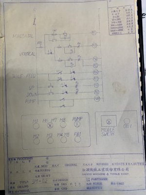
SM-G2 Control Wiring.jpg
 
Back
Top