- Joined
- Sep 22, 2010
- Messages
- 7,223
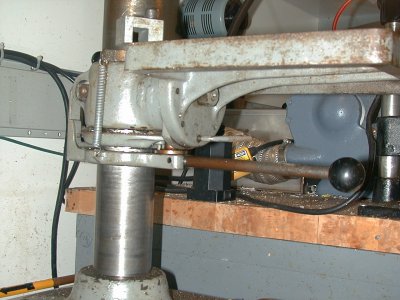
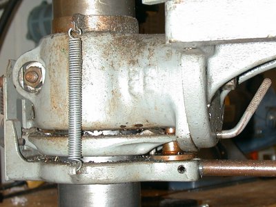
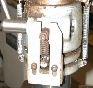
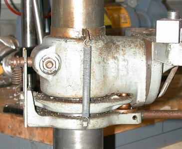
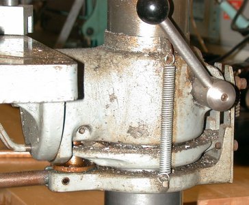
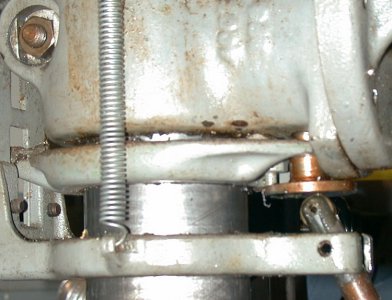
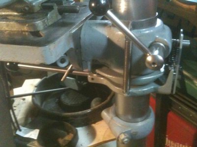
Installation:
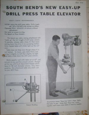
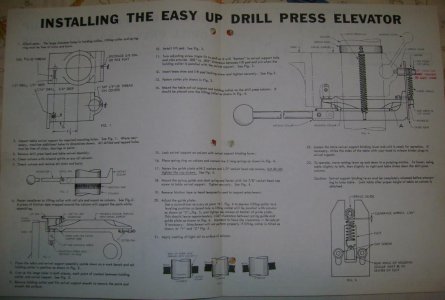
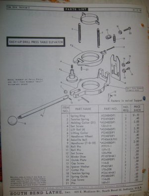
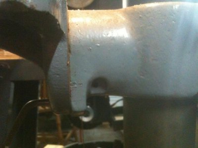
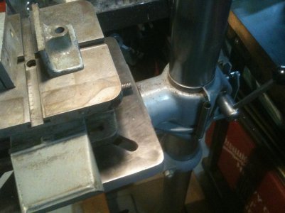
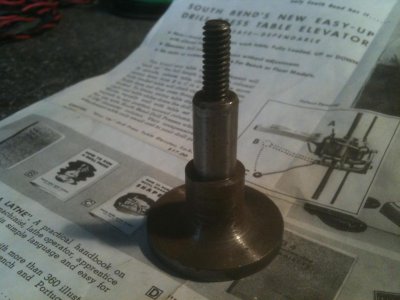
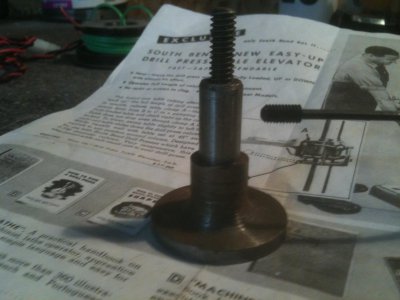
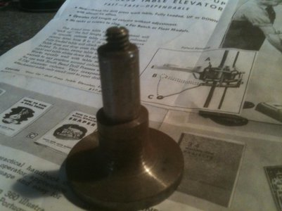
Chase the threads in the casting for the setscrew, drill out 7/16 hole in casting for good fit of contact plate, (it is just a little tight). Affix safety/stop collar, then begin stacking parts on the column. Stack as shown, then place main table.Next, attach rear bias spring, which is very tight . A little juggling to get the contact plate in place, then on to the spring retainer ring on top of the table collar. Dive back in once to adjust the contact plate that the roller bears against, as it is adjusted too short to allow the upper cast ring to"walk" correctly. The contact plate pushes on the steel pin hanging from the middle plate. (see the close-upside view photos above). Those side springs are very taut, too. (Note that the mis-adjustment resulted in very high lever force for movement -- so much so you can see the casting bend when viewed from the side. Table would also not descend, due to insufficient clearance.) The table walks right up at about an inch a stroke.While lowering the table does work by "wiggling", a much more controlled descent is obtained by slightly separating the middle ring from the bottom of the table collar. Doing so, and providing slight pressure on the back of the collar, results in a nice glide down the column. (No doubt aided by a coat of wax applied after clean-up). You can go too fast, and the descent develops a "shudder", but controlling that is easy. Curiously, the action was not nearly so smooth when lifting the front of the table during descent. You can make a lever that accomplishes the combined action of separation and downward pressure... there's lots of convenient places to attach an element like that to the assembly. The only "downside" so far is, if you are considering facing the bottom of the table to relative flatness, and adding an index hole, so that you can leave an x-y table and vice permanently attached to the (newly-trued-up) bottom, while still having the top free for more pedestrian uses, and need the vice/table, and flip it over, the actuating lever is in the way.
For those building the attachment,here are a few dimensions:
The published diameter of the drill press column is 2.730".
The actual diameter is 2.727"
The hole bored in each plate is nominally 2.732", and it appears to be bored "straight through", not angled.
The top plate is .63"thick, and the bottom is .64" thick. The cast plates are not machined ontheir top, bottom, or side faces -- only the main center hole, and the details on the appendages. So my analysis of "straight through" boring is based on no real reference surface. When placed on the column, the plates can be rocked an estimated 5 degrees included angle. The overall length of each plate, front-to-rear, is nominally 6".
The section of the "roller contact plate" that extends into the table collar casting is 7/16 in diameter. It is retained by a 10-32 hex set screw inserted from the side of the casting.
There's a hole at the very back of the table collar casting that is for the bolt that retains the "bias spring", which provides constant upward pressure on the upper ring.
