-
Welcome back Guest! Did you know you can mentor other members here at H-M? If not, please check out our Relaunch of Hobby Machinist Mentoring Program!
You are using an out of date browser. It may not display this or other websites correctly.
You should upgrade or use an alternative browser.
You should upgrade or use an alternative browser.
Sb Drum Switch Help Needed
- Thread starter Pinresto
- Start date
- Joined
- Jun 12, 2014
- Messages
- 4,817
These may be helpful files to review for wiring the SB if you know the original color of the motor wires. This information is from the following sites:
http://www.practicalmachinist.com/v...nas-drum-switch-instant-reverse-motor-179232/
http://www.wswells.com/data/wiring_info/index.html
http://www.practicalmachinist.com/v...nas-drum-switch-instant-reverse-motor-179232/
http://www.wswells.com/data/wiring_info/index.html
Attachments
- Joined
- May 23, 2014
- Messages
- 100
These may be helpful files to review for wiring the SB if you know the original color of the motor wires. This information is from the following sites:
http://www.practicalmachinist.com/v...nas-drum-switch-instant-reverse-motor-179232/
http://www.wswells.com/data/wiring_info/index.html
I've seen these pages but I don't know what wires are 1,2,3,4,etc
- Joined
- May 23, 2014
- Messages
- 100
Pinresto (Please sign all posts with your real name),
First, lets sort out your switch. Shown below is what is (according to Internet sources) the switching diagram of your C-H switch, but as I have less than total trust in anything found on the Internet, lets first confirm this. You will need either an ohmmeter or at least a continuity tester, which can be something as simple as a battery in series with a lamp rated for the battery voltage, and two wire leads coming off of the battery in series with the lamp.
Ignore the three terminals (screws) running from top to bottom of the switch's terminal board as they do not seem to have anything connected to them. Also ignore the L1, L1 and 4 stickers on your switch. The left three terminals, from top (the end with the handle) to bottom are 1, 3, 5. The right three are 2, 4, 6. With the switch in the OFF (center) position confirm that no terminal is connected electrically to any other terminal. Move the switch lever to the left and confirm that 1 connects to 2, 3 connects to 4, and 5 connects to 6. Move the switch to the right position and confirm that 1 still connects to 2, but that 3 now connects to 5 and 4 now connects to 6. If that all checks out, then the diagram is correct for your switch.
It is also correct for your motor so long as you realize that the only difference between a split phase motor hookup and a capacitor start motor hookup is that in series with the start winding is the start capacitor in series with the centrifugal switch. And that it makes no difference in which order the start winding, switch and capacitor are connected so long as they are all three in series, not in parallel.
Now to your motor. 7 wires cannot work. There should be either 6 or 8. You will have to take it back apart and figure out where you went wrong.
There should be two wires for the START winding. It doesn't much matter which is START and which is FINISH as if the motor starts backwards you can always fix it by swapping the two wires on the switch. One of the wires probably goes to one end of the start winding and the other to either the switch or the capacitor. But it would work just as well if one went to the switch and the other to the capacitor so long as the other side of the switch and the other side of the capacitor each went to one end of the winding (not both to the same end, of course).
There should be two wires going to the first RUN winding and two more going to the second RUN winding. Furthermore, you need to know which of each pair of wires is START and which is FINISH of their respective windings. If you have lost that information, determining which is which is most likely beyond your capability because of lack of the necessary test equipment if for no other reason. So you will have to determine it by cut and try. However, if you can see where the wires go into the coils, if one is obviously on the side of the coil nearest the armature and the other clearly on the outside, then the first is probably START and the second FINISH. In the attached diagrams, T1 and T2 are START and T3 and T4 are FINISH. If you can't determine which is which, then all that you can do is wire it up at random, plug it into a fused circuit with no larger than a 15 amp fuse or circuit breaker, and turn it on. If it immediately starts, you guessed right (even if it runs backwards - that is another guess). If it hums loudly and doesn't immediately spin up to speed, turn it back off immediately. Unplug the motor and swap the two wires from only ONE winding, not both. And try it again. Then, if it runs backwards, stop it, unplug it, and swap the two start winding wires.
Finally, the 7th wire. Presumably, this goes to the thermal/overload circuit breaker mounted in the motor. There are actually two terminals on a thermal breaker. Either you failed to bring out an 8th wire for the other side of that breaker, or the other side is connected to one of the four run winding wires. What to do depends upon which case you find and whether you are connecting it for 120V or 240V. Rather that writing four fixes, I am going to wait for you to investigate and see what you find and which voltage you are hooking it up for. But I will say that the thermal breaker should be in series with the run windings whether they are paralled for 120 V or seriesed for 240V.
I tries to check my switch but nothing matches that diagram you posted. I assume your diagram only has 6 terminals because the center three terminal are n/a? The model number is what's listed on my switch but the contacts do not match at all.
- Joined
- May 23, 2014
- Messages
- 100
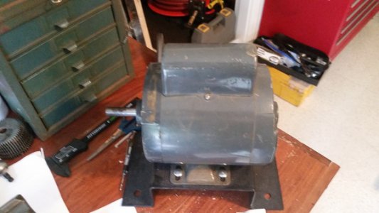
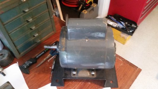
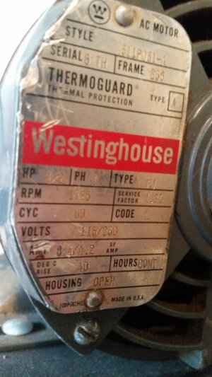
I have another motor I might be able to use. Would you please take a look and let me know if it will work? [URL=http://s1199.photobucket.com/user/Duketony75/media/Mobile%20Uploads/20150720_092101.jpg.html]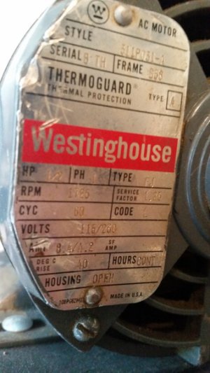 [/URL]
 [/URL]
- Joined
- May 23, 2014
- Messages
- 100
- Joined
- May 23, 2014
- Messages
- 100
Success!!!
It now works perfectly. I believe the first switch I was using had a problem. I'm going to see if it can be rebuilt.
Thank you Robert D. I could not have done it without you. Now I can actually use this lathe and I'm very excited about that. I would like to know if the second motor I posted will work for this application. It's not as old and it runs smoother. In the future I may switch to it.
Thanks again Robert and all those who commented.
- Joined
- Jun 12, 2014
- Messages
- 4,817
If you are looking for a lathe replacement motor, I would suggest going with a TENV type motor as opposed to an open frame type like your Westinghouse. The sealed TENV motor will not get contaminated with metal swarf and lubricant. Also beware that single phase motors do not do well with repetitive on-off cycling over a short period of time, three phase do not have this issue. One could also consider using a 3 phase motor with a VFD if one needed more speed control, alternatively a DC motor with a speed controller.
- Joined
- Dec 25, 2011
- Messages
- 10,513
Pin,
First, just as an FYI, if you hover your mouse pointer over your User ID near the top right of the screen, a menu should appear. Slide the pointer down to Signature and single click. You can put your given name or however you prefer to be addressed in that, save it, and it will automatically appear at the end of each of your posts and PM's. You can also, if you like, add your "brag list" of significant machines that you own.
Now, yes, the other motor that you have would work fine.
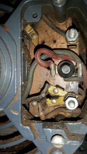
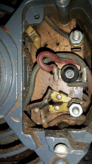
I don't know what the (1) and (2) are, either. But if there is a terminal board in the end of the motor as there is in your other motor, check whether there are terminals marked (1) and (2), like the (3) and (4) on the terminal board in your other motor.
On the two switches, first the two black wires running across the terminal board in the switch you were first trying to use are not jumpers, if that's what you were talking about when you asked whether you should remove the jumpers. Those are two of the six wires connecting the actual switches buried in the unit to the terminal board. That's how I knew that the three center terminals were all NC. There are no wires soldered to them.
Second, with drum switches with a 6-terminal terminal board there are three common configurations, at least for the ones that were originally US made. One is as the diagram I sent, with 1 connected too 2 in both FWD and REV. The second is essentially the same as the diagram I sent except that it is 5 and 6 that are connected in both FWD and REV. So try that pattern. It is the same as the pattern that I sent if you turned the switching pattern over, putting the handle nearest the terminal that were 5 and 6. The other is as the diagram attached below. If your first switch doesn't match the upside-down version then see whether or not it matches the Furnas R1. If it does, I recommend that you switch switches as it is safer.
Note that in the first diagram that I sent, one side of the AC line is always connected to one end of one of the single-phase windings. This is like the Furnas R44 switch. The Furnas R-1 disconnects both line leads from the motor for Single Phase motors (Split Phase and Capacitor Start). But it does not disconnect all three phases from a 3-phase motor. On the other hand, the R-44 disconnects all three phases of 3-phase but not both lines with single-phase. So for single phase capacitor start motors, you should use the R-1. And for 3-phase you should use the R-44. Or equivalent in each case.
I don't know what the second wire coming off of the overload breaker is. Unless is is an NO (Normally Open) contact and used for something like a remote motor fail indicator lamp. What did you do with the 7th wire?


