Select Mill Improvements

wrenchguyrich

Registered
Registered
Joined
Apr 3, 2021
Messages
18
Bought the Select mill in August 2020.
 

Attachments

  • 20200809_113657.jpg
    20200809_113657.jpg
    157.3 KB · Views: 79
  • 20200809_113850.jpg
    20200809_113850.jpg
    189 KB · Views: 80
Last edited:
Offloaded it at my place of employment as it was almost 1000 lbs. It would have to be disassembled to get into my manshed. Took the motor apart and changed the bearings just because. Fixed up the wiring on the start switch as the insulation was poor. Armature shaft on the oem motor has 10-24 m/screw in end. If a reverse switch is used, there is a possibility that screw will come unthreaded which could get messy.
 

Attachments

  • 20210124_105003.jpg
    20210124_105003.jpg
    233.8 KB · Views: 51
  • 20210124_105008.jpg
    20210124_105008.jpg
    256.7 KB · Views: 53
  • 20210120_144014.jpg
    20210120_144014.jpg
    266.1 KB · Views: 51
  • 20210120_143346.jpg
    20210120_143346.jpg
    260.5 KB · Views: 55
  • 20210130_151757.jpg
    20210130_151757.jpg
    209.1 KB · Views: 49
Last edited:
The guy I bought the Select mill form had built a 5.5" elevated base to make the height a bit more comfortable. I wanted to build a wheeled base for the mill and was playing with designs using material on hand. Settled on the last one and notched the ends of the 1 1/2 x 3 tubing for the end plates on the mill of course. Amazing what you can do when you have the tools.
I opted for 6" casters as I had 2 rigid casters on hand. I thought the additional 2" of height wouldn't hurt over the other base.
Did I need to make it so wide? Probably not, however more than a few comments online about base side rails too close to mill base and catching lots of chips. I was concerned about the whole thing being tippy as it will be wheeled around daily, so I went for some additional width.
 

Attachments

  • 20220121_120340.jpg
    20220121_120340.jpg
    370.7 KB · Views: 70
  • 20220125_151546.jpg
    20220125_151546.jpg
    517.5 KB · Views: 64
  • 20220129_145845.jpg
    20220129_145845.jpg
    282 KB · Views: 54
  • 20220423_175622.jpg
    20220423_175622.jpg
    563.3 KB · Views: 58
  • 20220515_114755.jpg
    20220515_114755.jpg
    373.4 KB · Views: 59
  • 20220430_102352.jpg
    20220430_102352.jpg
    171.3 KB · Views: 69
  • 20220515_133552.jpg
    20220515_133552.jpg
    163.7 KB · Views: 67
Last edited:
It appears the first 2 pictures didn't upload properly?
 
Somewhere in this period of time I picked up a 56C 1 hp tefc 1750 rpm 3 phase motor and then purchased a vfd to team it up with.
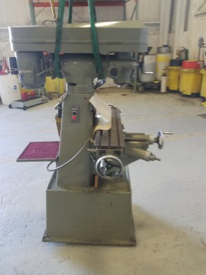
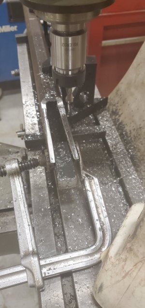
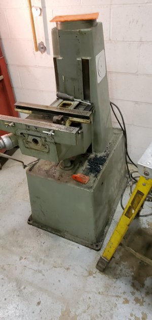
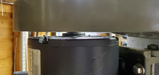
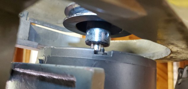
However, it turned out that the C-face motor frame doesn't really fit on the mill that well as the c-face end bell hits the belt guard.
I'm not sure if I have a picture of it installed. I keep looking. Because motor hits belt guard, you have very little movement or swing on motor to swap belts.
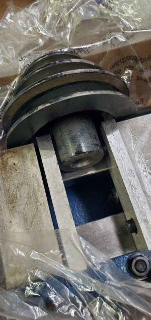
I then picked up a metric M80 1 hp 1740 rpm motor for a decent price, but again it doesn't really fit that well either as the motor mount plate isn't wide enough to accommodate an M80 base, so some kind of adapter plate will probably need to be made. Additionally, the mills pulley needs to be bored out to 19 mm, which I did't want to do as there is no turning back. One also needs a metric keyway broach to complete the job, or 3/16" broach, neither of which I have, and make a step key. Step pulleys with 3/4" bores are available on the net, however I've never found one with the wider belt grooves, ie 5L. Would still need a step key. I concluded that the money for the step pulley would be better spent on the appropriate motor.
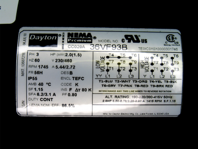
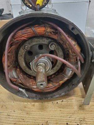
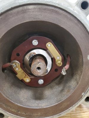
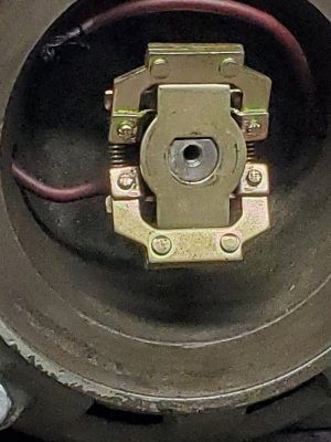
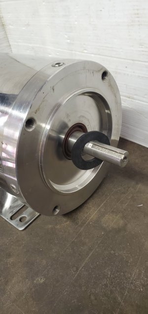
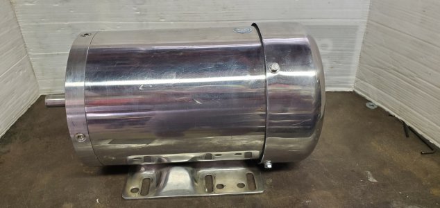
I said to self, a 2 hp motor would really be nice, so what would it take to get there? $290 all in for a Dayton 56H frame 2 hp tefc 1750 rpm 3 phase motor. So, this one is a nema premium rated motor, apparently all nema premium motors are VFD compatible. Taking motor apart, it looks to be made by Weg.
After seeing how the 56C motor hit the belt guard, I spent many hours researching what would or wouldn't fit.
To be continued.
 

Attachments

  • 56c1.jpg
    56c1.jpg
    147.1 KB · Views: 52
  • 56c4.jpg
    56c4.jpg
    382.2 KB · Views: 52
Last edited:
Looking good! Just a heads up on Weg motors, they take a lot of power to start, so over rate your VFD when you select it. Typical Weg motor inrush is 2x rated HP or better. They are good motors, they just have higher inductance that requires a bigger kick. Keep the posts coming!
 
Time to bring the mill home in pieces. I needed just the base bolted to the wheeled assembly in order to roll it up a set of borrowed atv? ramps from work. Hand truck all the rest of the parts and fun begins.
Clean everything up and reassemble it in the manshed. Ratchet hoist to the rescue to pickup the heavy stuff.
The wheeled base is made from 1.5" x 3" x 0.25" wall for the side rails. Didn't need 1/4 wall, but it was on hand. The wheel plates are 1/4" flat 4" x 6". And the angle is 2" x 2" x 0.188".
 

Attachments

  • 20220520_060003.jpg
    20220520_060003.jpg
    275 KB · Views: 56
  • 20220528_150741.jpg
    20220528_150741.jpg
    127.9 KB · Views: 50
  • 20220515_131712.jpg
    20220515_131712.jpg
    187.3 KB · Views: 53
  • 20220507_104000.jpg
    20220507_104000.jpg
    117.3 KB · Views: 54
  • 20220507_100000.jpg
    20220507_100000.jpg
    153 KB · Views: 56
Last edited:
One thing that was goofy when it came time to attach the head. There are 7 T-bolts and 7 nuts for the head to column and the spindle and motor mount. 3 are different than the other 4, the 3 won't thread on but the 4 others will. Huh? 3 nuts thread onto a 1/2" nc bolt easily. The T-bolts are 1/2" - 12 tpi, not 13 tpi. Bsw threads, so the threads on the Select mill no doubt are Bsw and being very similar to Un threads they are more or less interchangeable. Except of course in 1/2" where the pitch deviates. Not sure how someone was able to get 13 tpi nuts onto a 12 tpi bolt but they did. Seems to me they had to be wrenched off all the way. Grizzly tools still offers the 12 tpi nuts as parts on there older version of this machine. Thanks, Griz. See picture.
 

Attachments

  • 20220613_143106.jpg
    20220613_143106.jpg
    304 KB · Views: 50
  • 20220613_151603.jpg
    20220613_151603.jpg
    182.7 KB · Views: 51
  • 20220613_151016.jpg
    20220613_151016.jpg
    1.3 MB · Views: 53
  • 20220613_143610.jpg
    20220613_143610.jpg
    356.7 KB · Views: 54
Last edited:
The mill is now assembled and the new 2 hp motor has arrived. The oem motor step pulley has a set screw 180* opposite the key. This isn't the way it should be, so let's setup in the vise with a spare single 3" pulley on motor. Drill and tap 2 set screw holes, 1 on top of the key and 1 at 90* to key.
As I mentioned earlier about the c face motor end bell hitting the belt guard, the picture shows the clearance between the new motor and the belt guard. Also, note the shoulder on the motor shaft, it protrudes about 3/8" past the motor end bell. This was important to me to get the belt guard clearance. Sure, I could have drilled new motor mount holes and pulled the pulley away from the shoulder some, I chose not to. If you are shopping for a motor for the Select mill, pay heed to the engineering drawings that most manufacturers supply. The Select mill is setup for a 56 frame motor.
 

Attachments

  • 20220928_090045.jpg
    20220928_090045.jpg
    253 KB · Views: 51
  • 20220928_141847.jpg
    20220928_141847.jpg
    494.9 KB · Views: 48
  • 20220921_093131.jpg
    20220921_093131.jpg
    224 KB · Views: 48
  • 20220921_084702.jpg
    20220921_084702.jpg
    112.9 KB · Views: 47
My Select mill was built in 1979, and its time for an upgrade electrically. Including VFD and a vfd rated Tefc motor, circuit breaker, contactor, some line filtering and etc. The ac input line filter is just visible under the din rail with 10 amp cb and 25 amp contactor.
Any motor running at half its rated speed will have compromised cooling. The addition of a 120 mm puter fan, 127 cfm, on the bottom of the motor fan guard should take care of that. Not sure why the motor fan guard had 3 holes, but they were sure convenient to mount the pwm fan. Found a 2 fan pwm thermometer control module, comes with 2 temperature probes. The pwm control of the fan is nice as it may start off at lower speed first, rather than maxed out and noisy.
Opened up the motor and installed 1 of the probes on the motor windings secured with small ty-raps. The other fan will be in the control enclosure. The din rail 240/12 volt p/supply is for the fans, as the vfd 12 volts is rated 200ma max. The small fuse holders are additional protection for the 240 volt contactor coil and p/supply feeds, otherwise there is 10 amps potential on the 20 or 22 gauge wires.
 

Attachments

  • 20221102_160913.jpg
    20221102_160913.jpg
    154.8 KB · Views: 47
  • 20221102_165120.jpg
    20221102_165120.jpg
    255.8 KB · Views: 54
  • 20221102_165114.jpg
    20221102_165114.jpg
    245.6 KB · Views: 53
  • 20221023_091422.jpg
    20221023_091422.jpg
    223.2 KB · Views: 51
  • 20221017_141334.jpg
    20221017_141334.jpg
    232.8 KB · Views: 51
  • dayton4.png
    dayton4.png
    1.2 MB · Views: 45
  • dayton3.png
    dayton3.png
    1.4 MB · Views: 44
  • dayton mtr.jpg
    dayton mtr.jpg
    51.1 KB · Views: 47
Last edited:
Back
Top