Servo 140 limit switch wiring diagram...

FOMOGO

Active User
H-M Lifetime Diamond Member
Joined
Sep 2, 2013
Messages
5,099
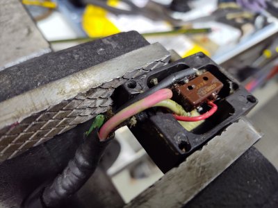
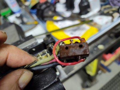
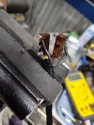
Have been going through Servo 140 power feed on my Acra mill. Replaced the power switch, and adjusted the rapid switch so the unit now functions as it should, but no joy on the limit switch. It has four wires red,white, black, and blue, with the blue having been cut at the switch. Does anyone have a schematic for the switch, or possibly take the cover off their limit switch and let me know how it's wired. Thanks, Mike
 

Attachments

  • IMG_20240318_111501337.jpg
    IMG_20240318_111501337.jpg
    389.2 KB · Views: 36
  • IMG_20240318_111541627.jpg
    IMG_20240318_111541627.jpg
    291.5 KB · Views: 32
  • IMG_20240328_124843081.jpg
    IMG_20240328_124843081.jpg
    199.7 KB · Views: 36
Those are Micro switches- they should be marked as to the contacts:
normally open or NO
normally closed or NC
and common or Com
 
No, wasn't working at all until I replaced the power switch, then no stop function at the limit switch. Mike
 
I don't see the little "leafs" or actuator arms on the switches- Need to see a shot in the box
to see how the plunger mechanism works- maybe a very early model or pieces could be missing
Looks like you might need to rebuild the limit switch box or replace it- they are available on Ebay

That diagram doesn't seem to show the limit switch wiring- if it does my pea-brain can't follow it LOL
 
Last edited:
I don't see the little "leafs" or actuator arms on the switches- Need to see a shot in the box
to see how the plunger mechanism works- maybe a very early model or pieces could be missing
Looks like you might need to rebuild the limit switch box or replace it- they are available on Ebay

That diagram doesn't seem to show the limit switch wiring- if it does my pea-brain can't follow it LOL
You're right Mark, that's my screwup. Thought it was in the diagrams in the upper right, but it just shows one of the leads coming from the limit switch, not the limit switch itself. Apologies.
 
No need to apologize- I wonder if they had a separate schematic for the limit switch?
Or if it is indeed the two switches in the upper right hand side of the upper diagram? If so it's not very clear
 
Last edited:
Back
Top