Small face mill using tangential cutter

o.k., maybe i get it now: the two angles are not in the same orientation. is the 12° from axis of rotation? but then the narrow end wouldnt be the cutting edge. on the pict. it looks like the angles line up (30-12=18°)

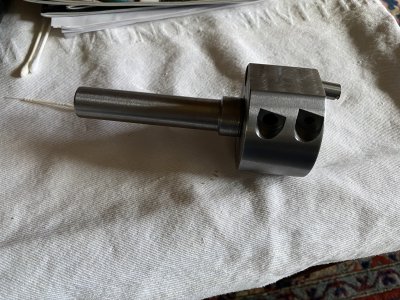
this is a cutter i made:

View attachment 315875View attachment 315875

its originally for a radius attachement but it cuts and faces wery well.

(how to delete the second pict.?)
Nice! In regards to my remark on making something along the same lines, is the rod vertical or does it have a small forward (toward the headstock) tilt angle? It's hard to tell from the photo. Based on where the fixing screw is, I'm guessing it is vertical. Altogether possible I'm wrong in that.
 
yes, tilted 5° i think. i made another rod out of carbide that was concave on top and that was very good for parting off. i never use the contraption though.

so are your angles "paraller" or not?
 
so are your angles "paraller" or not?
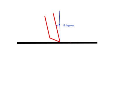
Mathematically speaking, no. But they have a specific relationship, and it's all relative to the plane of the work. A drawing is easier to show the relationship.

tangential.jpg
In this side-view drawing, the horizontal black line is the plane of the workpiece. The red lines show the cutter. In this view, the plane of the ground facet also is a line. So the relationship is as follows: the plane defined by the facet _would_ be parallel to the workpiece if it was rotated 30 degrees counterclockwise around the tip of the cutter.

In this drawing the cutter will move from left to right as it removes material from the work. That's probably backwards from how it works with a real tool rotating clockwise but the drawing was for purely pedagogical purposes :grin:

It also can be seen from the drawing that the tip of the cutter will contact the work first, even if it's rotated around its own axis. If this is done within reason, we'd have a cutter that cuts with some shearing action involved. Of course, rotating it by more than +/- 90 wouldn't work. Exactly 90 degrees might cut slots with square bottoms but my gut feel is that the cutting action would be pretty strange. Now I've thought of that I guess I have to try it...
 
I have some follow-up results regarding the tool I made. I noticed that the cutter dulled pretty quickly when machining steel so I made another grinding fixture that puts a 17 degree angle on the HSS rod, rather than 30 degrees. The idea was to get a more-robust cutter by changing the included angle from 60 degrees to 73 degrees. The holder geometry is the same, tilting the rod 12 degrees from the vertical. As a result, the cutter has 5 degrees of back relief relative to the plane of the work.

I haven't tried the new cutter angle on steel, but it doesn't work all that well on aluminum, at least not on material that is wider than the cut path. It sort of shears the aluminum, leaving a rough, raised edge. Multiple passes across the entire surface work OK, but the strange cutting forces don't produce a very good surface finish. I also can tell that the tool is working harder to make the cut. I wasn't going for a high DOC, either -- .005" per pass.

I'll try rotating the cutter in the holder to different angles and see what happens.
 
I made a similar flycutter and agree that getting the right cutting angle is a trial and error sort of thing. I played with various grinds before getting it about right. It’s still a work in progress because whenever I use it....I start farting with the cutter angle again. ;)
 

Attachments

  • 5747B283-294F-4633-B1D6-57CC04422E05.jpeg
    5747B283-294F-4633-B1D6-57CC04422E05.jpeg
    1.1 MB · Views: 86
I made a similar flycutter and agree that getting the right cutting angle is a trial and error sort of thing. I played with various grinds before getting it about right. It’s still a work in progress because whenever I use it....I start farting with the cutter angle again. ;)

Thanks for the feedback. Your version looks quite similar to mine. I do have a question regarding the cutter itself. It looks like you ground a sort of hook or (for lack of a better word) chip breaker gullet into it. Is that correct?

Also, I'm wondering if the flat you milled into the holder was done to improve the balance, or for some other reason. I like the idea of improving the balance.

Thanks!
 
Homebrewed. I apologize for such a long delayed response. I just totally missed that you had questions about my little cutter.
So, here goes. Anyway I forget the birth of my cutter but FWIW, I used a 3/8” round HSS tool for my cutter. So I did put a curved grind on my cutter and it does seem to act as a chip breaker. I get a pretty nice finish when using it on aluminum. But I’m also taking fairly small cuts. And I’ve experimented with both the angle of attack of the cutter. My tool is still a work in progress every time I use it.
 
Like the idea, especially using a round cutter, which should improve the finish like on some of the shaper and lathe tools.

It should be possible to modify a flycutter head to do this, correct? Drill a hole at the correct angle and add a set screw. I seem to have ended up with a gazillion* different fly cutter heads.

* That's machinist for eight.
 
Yeah, I saw someone else's build where he used a round cutter. Just easier to drill that round hole than make a square one. But since its round, I did use two set screws. And yeah, just drill at the angle you want. All this said, the ones you see sold online tend to be pretty proven designs. Thats the ones like this.

FLYCUTTER
 
So, now I've got a question.
Could I take an existing fly cutter, bore a hole into it, add a couple of set screws and make a tangential cutter out of it?
Use a busted 1/4" end mill shank for the cutter perhaps?
 
Back
Top