Small hold down clamps for my HV-6 rotary table

WobblyHand

H-M Supporter - Diamond Member
H-M Lifetime Diamond Member
Joined
Dec 18, 2019
Messages
7,223
In a separate project thread, made an 8" diameter fixture plate for my Vertex HV-6 rotary table. I drilled and tapped the plate for M6 screws.
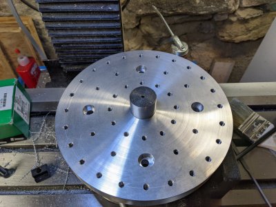
PXL_20220303_014746720.jpg
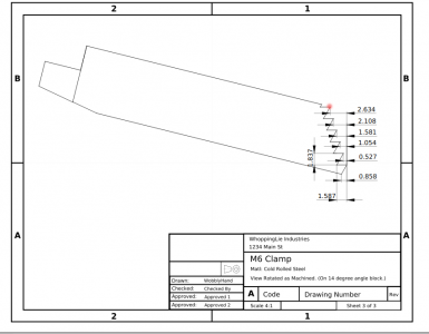
I need some clamps for the table, so I thought I would design up some and machine them. The modeling was a little trickier than expected, but I came up with a way to dimension the steps. I want to reuse my existing step blocks, so I needed to make the clamp steps consistent with the steel step blocks. Here is the drawing for the clamps. I'm not positive on the length, so I will make a prototype out of aluminum to further refine the design. There are a lot of interesting setups to make this, and plenty of places to screw up, so it will be good to do this on an easier machining material. Once the design is validated, I will make four clamps out of cold rolled steel.
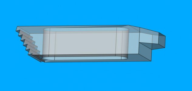
hmproj_m6clamp.jpg
This is an example of a simple part that previously, I wouldn't even thought about. Now that I have drawn this, and imagined how to machine it, I am impressed with what goes into such a part.
 

Attachments

  • m6clamp.pdf
    630.3 KB · Views: 8
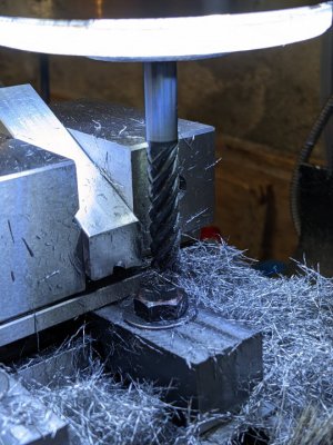
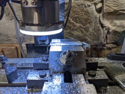
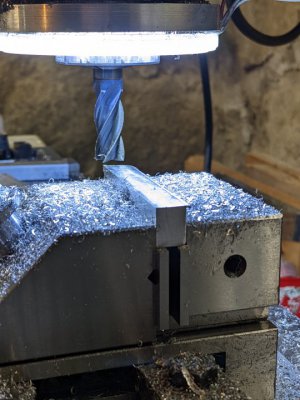
Made a little progress on machining the prototype. Came to a dead stop, realizing I had left out a dimension. Furthermore, the dimension is sort of a virtual one to a point that doesn't exist in the final part. Cut the scrap to rough size, machined the height and depth, but left the length long. Used a 30/60 block to cut the start of the steps. Installed the dovetail cutter with a bit more stick out than I wanted, and stared at the drawing. Yeah, no starting point! Hmm, going to have to do some trig to figure this out. Don't think FreeCAD is going to help, unless I can create a magic point I can reference to.
PXL_20220403_173907627.jpgPXL_20220403_181801614.jpgPXL_20220403_185034499.jpg
Fell into an n-dimensional hole. Be back in a bit. (I hope!)
 
It turns out that the vertex, shown by the red dot in the drawing is around 0.085 mm lower than the corner would be. I'm not going to really worry too much about this. I guess I will touch off on the actual corner, and drop the tool by 0.085 mm and make the first dovetail cut. If I am off a little it just won't matter.
m6clamp_rotated_w_dot.png
Still thinking about redoing the dimensions. They are correct, but they require too much thinking when in front of the machine, might change them so it is easier in the shop.
 
Instead of changing the drawing, I made a sort of G code for humans crib sheet, which I will attempt to attach. It's merely a set of instructions of movements and setting the DRO points to get the desired profile. This is a LibreOffice spreadsheet. If anyone wants it, I can save as an xls file. I am hoping to try this out in a day to make the steps in the prototype clamp.
 

Attachments

  • m6clamp_machining_sheet.ods
    22.4 KB · Views: 3
Thanks for posting all the dimensions and proses making the clamps . Right now I have a set up on the mill that I’m trying to cut a large 55 degree dovetail for my steady rest using a fly cutter with a bit ground and set at 55 degrees. Not finished but I think it will work so I might try using that type of setup for the clamps .
 
It turns out that the vertex, shown by the red dot in the drawing is around 0.085 mm lower than the corner would be. I'm not going to really worry too much about this. I guess I will touch off on the actual corner, and drop the tool by 0.085 mm and make the first dovetail cut. If I am off a little it just won't matter.
View attachment 402915
Still thinking about redoing the dimensions. They are correct, but they require too much thinking when in front of the machine, might change them so it is easier in the shop.
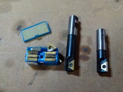
you could use a sine bar and a threading endmill to make that cut.. all at one time..
 
Thanks for posting all the dimensions and proses making the clamps . Right now I have a set up on the mill that I’m trying to cut a large 55 degree dovetail for my steady rest using a fly cutter with a bit ground and set at 55 degrees. Not finished but I think it will work so I might try using that type of setup for the clamps .
Glad my write up is useful. I've learned a lot from people on HM, so it's my job to pass some of that knowledge back onto the forum.

Mind you, I haven't milled the steps yet. Got some non machining activities today, so think I will finish machining the prototype tomorrow.

I did come to the realization that my DRO has 5 micron scales, (duh) so I need to adjust the dimensions to accommodate that. Think it may not matter, but I should check for error accumulation. Also my quill DRO is only 10 micron display. Reality and drawings have collided. Reality will win.
 
Ah, light goes on. Appreciate the picture.

Unfortunately, I think the teeth don't have the correct shape. The included angle is 60 degrees, but the sides of the triangle are unequal length for a step block. The cutter shown has equal length sides, and no offset. This is not to say that such an insert doesn't exist, but the cutter shown doesn't seem like it would cut the step tooth profile.
 
Back
Top