Smithy Midas Combo Stepper feed project(s)

Inferno

Registered
Registered
Joined
Feb 24, 2019
Messages
927
I figure I might as well call this a project and keep it all together.

Back story.

I HATE the little handwheels on my Smithy Midas 1220. They are flimsy and have too small of a radius for my taste. I'm not necessarily going to replace them. I just hate them.
I also hate that I can't change the leadscrew speed on my machine without changing gears. The gear change steps are more difficult then they need to be but they work, I suppose.
I don't like breaking the sacrificial gear hub when I screw up and forget to unlock the slides. Especially since the machine, and the parts, are discontinued by Smithy. They might still be available in China somewhere but I didn't find them.
And I hate how slow my Y-axis feed is and how I have to used the lathe drive just to have the power feed when milling.

The key, remove the manual drive. Replace with stepper drives. That's my goal.
(I evensually plan to replace the main motors as well)

This last week I was making some parts on the mill and the number of cranks I needed to make on the small handwheel just wore my forearm out. I eventually went to a hillbilly feed.

The following will be to document the changes I'm making. I will try to include tooling and processes but I'm bad about that stuff.

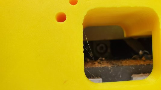
The first picture is of the hillbilly feed I used.

20230605_203904.jpg
 
The idea is that I will add a stepper to the main leadscrew. That was going to be for X and Y axis travel but I decided later to add the Y-axis drive separately. I have a few reasonds for doing this but I'll keep those to myself.

I'll show pictures along the way.

20230610_125915.jpg
20230610_125948.jpg

That's what I'm working with.
I already removed the dial indicator for the lead screw. That is where I'll put the follower gear for the stepper driver.
I'm going to put a 2:1 gear set there using a timing belt for accuracy. The stainless steel bolts shown are for my DRO and I will utilise that mounting spor for the Stepper mount.
I'm still working on an adjustment method but that's going to be the least of the issues, I'm sure.

Below shows the difference in width between the follower gear and the dial indicator.

20230526_105222.jpg

I machined it down to the same width as the dial indicator and will add a new set screw inside the gear. I also need to machine a keyway into the follower gear to match the keyway in the dial indicator.


20230528_150818.jpg

In order to put in a keyway, I bought a 4mm broach. I don't have a kit so I'm going to make the part that guides the broach. I'm making it out of brass since it will be a one-use item. I'm waiting on the broach before I cut the keyway in the guide since I need to know how deep to cut it.

20230528_181019.jpg

20230610_132206.jpg

That's where I'm at for the X-axis lead screw mod. Waiting for the broach and belts (I ordered different sizes) to get here. Then I can start building the mount.
I should note that the way I'm building this, the handwheel will still be functional but, honestly, I don't think I will ever use it.
 
The Y-axis will be harder.
I will have to disassemble a lot just to get measurements and then reassemble to make the parts. Reassemble to fit the parts, reassemble to make any corrections. I see at least 3 cycles in the process but this is because I'm putting the stepper motor in back of the slide rather than the front and I'm replacing the lead screw with a ball screw. There will be a bit of fabrication involved.

The first stage, for me, on the Y-axis will be to build the motor mount. Easiest at this time because I'm still not spending cash these days and the ball screw will cost a couple bucks. I have everything else I need to start this part so it's a good time to work on it.

First I took measurements of everything I will need to match on the machine as best I can until I get the ball screw. The main mounting block is fine as-is designed now but the stepper mount plate will need to be adjusted, I'm sure.

The first iteration was 3D printed as a single block. Then I reprinted it with the mounting block and the stepper plate separate. I printed the stepper plate again as how it will connect when done. When installed it will completely cover the main mounting block bolts. The only reason I'm doing it this way is to make it look cleaner. You can see the difference between the yellow and gray prints (I'm running low on yellow so switched to gray).

20230607_070826.jpg
20230607_070833.jpg

Here's the bullseye I'm tring to hit. It's closer than it looks but should be close. The goal is to have the exact same line as the original lead screw because I want to preserve the apron connection to the rail. In theory, unless I'm wrong after disassembling, the parts can be added to drive the ball screw with the apron gearing.
20230607_085750.jpg


20230608_233635.jpg
20230608_233648.jpg

I'll be using a steel flex coupler to drive the ball screw because I can't guarantee, myself, that I can get it all put together with zero tolerance. I'm going to shoot for .002" or less.
I could leave a little play on the stepper to plate connection to allow for closer adjustments and I'm considering it but I'd also like to keep the stepper locked in side to side and up and down so I'll see how that pans out.
20230610_105853.jpg
20230610_105902.jpg
 

Attachments

  • 20230607_085713.jpg
    20230607_085713.jpg
    257.8 KB · Views: 2
I do have a few options on the stepper drivers and motors. I already have a few. I'm thinking the GeckoDrive will be the driver I will use. For the motor, I have at least 6 of the ones shown in the picture. They are old stock though so if they cause too many problems I can switch to a different NEMA 23 motor. I have a few I've bought for other projects including 4 that are super strong. I shouldn't need anything super strong.
To control the driver, I will either use a pulse generator (on order. SHould be here in a couple days) or, at some point, switch to an arduino driver. I haven't written codein a while but I did cheat to see if ChatGPT would write it. It seems like it would be easy to cheat.
I think one of my current power supplies will work. I believe one is 15A and the other is 45A. I have a few others pulled from equipment that I could use as well as a couple PC chassis that I could steal from. That's not goin g to be a problem.

20230610_151613.jpg
20230610_151652.jpg

In this picture below is a LPT1 Connector for Mach3 but it's pretty much obsolete at this point. If I ever go to connect to a computer I will get the USB interface. They're not expensive.

20230610_151916.jpg
 
My first mount went horribly bad. Takes hours to do this with cleaning up each side and then machining the holes exactly right.
I start out with a crappy old chunk of aluminum cut from a 6 foot long bar.

20230615_130349.jpg
Then I machine all six sides to get it to the right size.
I needed to take over a quarter inch off one dimension, .070 off another and the length needed to be cleaned up on one side and a tab left on another.

20230611_210821.jpg

That is the rough cut with just one side to clean up before drilling.
The drilling is made with 5.2mm bits to make intoM6 threads. 8mm bores for mounting bolts. and counterbore to have them set below the surface to allow the motor plate to sit flush.

Without showing all the mistakes I made, this is to show the bracket I'm replacing and how I totally, somehow, messed up and had the holes drilled in the wrong place. I don't know how I made the mistake but I own it.
20230613_193458.jpg

I trashed that piece and redesigned the hole locations. I also eliminated the tab since the same result can be achieved a different, easier, way but this is the finished result of the new hole positions being drilled.

20230615_092412.jpg

20230615_092348.jpg

As you can see by the width left over on the counterbores, this is about perfect as far as being parallel with the plane of the holes vs edge of the piece. This is a very important thing for me because of what's next.

20230615_114935.jpg

I temporarily mounted the spacer to make sure the holes fit. One of the dimensions I measured for hole placement was weird. Most everything lines up in full millimeter distances but these were off by .4mm
I trusted my measurements and, despite only having .04 mm to work with, the holes lines up perfectly.
But, if you look carefully at the last photo, you can see the spacer block is not flush with the table. This is disappointing since all the bolts are square to the block and, well, perfectly positioned. I want to clean them up before it's all assembled at final but I can't shave the angle away before I get it all built and lined up because it will throw off all the other geometry. It's going to be a challenge going forward.

I also need to shave the ends. I left them deliberately long because they are the least critical part of all this and I didn't want to spend time on them if the holes didn't line up.

The good news is now I have exact positioning for the motor plate that will come later.

I also want to extend the keyed slots. Not so much that they will be keyed but I want to be able to remove T-nuts from the non-op side. Maybe just leave a shallow there or something.

Going to be a bit before I move too much further forward as I need to get the right ball screw and will need to have that machined custom.
 

Attachments

  • 20230615_114914.jpg
    20230615_114914.jpg
    474.4 KB · Views: 0
Last edited:
Today I finished cleaning up the ends. They were a little longer than the table, by design, so I got them to where they need to be.
I also added the relief for the ball screw to go to the stepper plate. Then I added a window for accessing the flex coupler. It's accessible from the bottom without the window but this will be easier. I will 3D print a plug for it down the road. Don't need chips getting to the ball screw.
The relief cut came out less desirable than I wanted it to. I might clean it up later. It's never going to be seen but it's still bugging me.

If you see the spot where it looks like my mill bit slipped, your eyes aren't deceiving you. That is exactly the type of problem I'm trying to eliminate.

Next up is to thread the holes for attaching the stepper plate.

20230617_175149.jpg
20230617_175216.jpg
 
I finally got my push buttons in. They were supposed to be momentary non latching. They are latching buttons. My mistake in not reading the fine print.

What to do, what to do.

Since I'm a tinkerer, I know how things work good enough to know I could probably find a way to eliminate the latching mechanism. So here we go.

The first thing I did was to remove the actual switch part. The contact mechanism.

20230627_172240.jpg

After that, I looked to see what needed to be removed for the latch. It's buried pretty deep.
The first switch I wasn't worried too much about destroying (I ended up getting it back together and working too).
The goal was to see if I could separate the parts easy enough to remove the latch mechanism. You know, find out how it works.

I don't really have a picture of a completely disassembled switch but in the next picture you can see the latch part that's brass. It's connected with a little wire piece so it won't just pull out. Lord knows I tried.

20230627_172340.jpg

And the next photo is the little brass latching part that needs to be removed.

20230626_172559.jpg

There's only one way that the part should be removed and that's by separating the metal threaded part from the blue part. They're crimped together really well. Surprisingly the aluminum housing is pretty robust so I had a hard time trying to pry the crimps enough to get the housing from the blue part.
As I said, the first one looked pretty bad but I learned how they work.

20230626_172526.jpg

What to do, what to do?

I decided the easiest way was going to go through the side of the housing and get access to the little brass latch.
Worked like a charm.
I locked it down in the vise and took shallow passes until I saw brass and then took a .005" pass after that.
Made easy work out of removing the latch. I did the first switch in a little over an hour trying to pry it apart.
The other 5 took me less than 15 minutes and that included putting a bit in the mill.

20230627_173626.jpg

20230627_174254.jpg

20230627_210931.jpg

20230627_211117.jpg

So now I have 6 momentary, NON LATCHING buttons. (I only needed 4)

After they're installed and I have the connector in place, and they're tested, I'm going to put shrink tube over the hole I made.
 
Back
Top