Straight Edge

What is wrong with a Dremel or other grinder? They remove too much in concentrated spots and way too fast.

It is good you have lots to time, because it takes a lot of time....

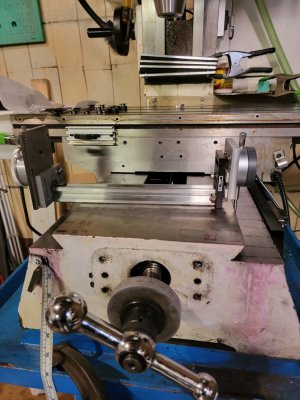
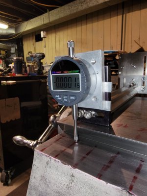
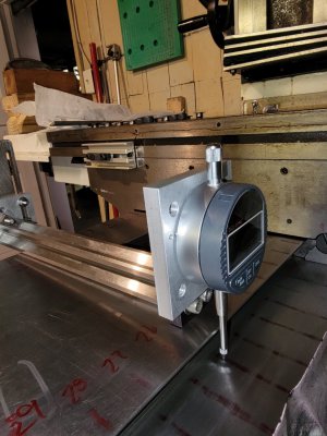
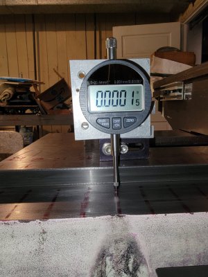
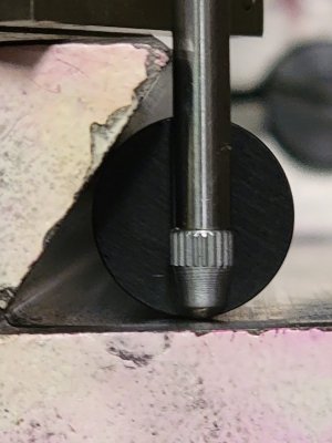
I have had a similar problem with my mill ways and I have been fixing it .... slowly.... not by scraping or to grinding, but by sanding. Use good water proof emery cloth. The way you describe thinks your desire is to remove 0.005" along the non-dipped rest of the way to bring it down to the dip. I have not attempted to take this out of the v-groove only the flat part of the way where the saddle rests and runs. Yes, my machine has hardened ways too, but you would be impressed at how fast it actually comes off. You are correct, the way to achieve this is to have a good measurement tool. Don't start until you figure this part out. In the case of my Mill I have a reference surface to work from. So I use a flat bar that rests on the reference surface and then use digital dial indicator (plunge style) gauge to measure the distance to the flat part of the way along the length of the way by sliding my flat bar along. The dial indicators yield quite accurate results. I can measure deviations on the few micron scale repeatedly! You also have to measure across the flat part, not just down the length. You want to keep it flat in both directions. I have also built a tool that does something similar, but measures the depth of the V groove, actually the distance between the two V grooves, between the two sides of the saddle. However, I have yet to try it out.

Patience is critical. Go slow with more time spent in measuring than in actual sanding.

Which part of your way dips? The flat part or the V? If it is the flat part you stand a chance. I would not try the V surfaces without an even more complex measuring tool. Check the tops of your Vs are they flat? If so you might use them as reference surfaces.

I found that these digital depth micrometers are quite accurate and very repeatable. Most importantly, they are affordable. They also sell a digital cable that will suck the reading right into Excel or Word at the click of a button. So you do not have to write it all down by hand. Clockwise Tools. If you think you want to go this route check out the micrometers and the cable... links below.

"Clockwise Tools Digital Indicator, DITR-0105 0-1 Inch/25.4mm, 0.00005 Inch/0.001mm Resolution, Inch/Metric Conversion, Auto Off" Amazon at $64. I have two so I can measure both sides of my ways at the same time.
Get the high accuracy 1" stroke version. There is one with auto off and one without. Your choice. It takes a 3V li-ion cell.
You will also find the cable at their store or via these links:


I was thinking a grinding stone would be more appropriate than a cutoff disc, precisely because it would have more surface area and dig less deep.
For that reason, scraping a twist or odd angle into the ways was more of a concern to me than digging in with the dremel. I think I'll need to weld a couple tabs to the middle of the I-beam before scraping them. One that I'll be able to bolt an arm to. Let the arm rest on the opposite V, press the straight edge to the unworn portion of the way, then bolt the arm solid in place.

@B2 , my lathe has hardened Vs with rounded tops on both sides. The tailstock also rides on double Vs. The original flaking is still present on most of the tailstock Vs, but only near the end on the saddle Vs.
 
my lathe has hardened Vs with rounded tops on both sides. The tailstock also rides on double Vs
A Picture or sketch might help my understanding. Can you post a sketch? Which part of your way dips? The flat part or the V? Can you use the tops of the two Vs as a reference surface to do the measurements. That is, where do you think you need to remove material to make things flat? If the tops of the V is not worn did you measure it to see if it was flat? Can we assume that the saddle and tailstock ways are not worn much or any?

I put the emery cloth on a block so as to make it flat. However, the sanding is slow enough that if you are doing lots of measurements you can just use a thumb as a pressure point. Blue the spots that are high and then sand off the color. For a while I put the emery clothe under a large (just fit on the way flat surface) flat magnet and then dragged it back and forth.....i.e. let the magnet provide the downward force over the area of the magnet. However, the sanding block works better as you can adjust the pressure distribution.

I will attach a few photos showing how I arranged the micrometers. This is an early photo, before I got the good Clockwise micrometers. The ones shown are bolted to the ends of a very flat bar used for optics. This bar sits on the very flat reference surface at the center of the mill bed (in one photo I wrote some position numbers on it with a red marker). So the micrometers hang off of the end and reach down to the way surface(marked with straight red lines (The lines are located about every inch). In one of the photos you will see a pin gage located in the V. I have built and someday will measure the distance between the two Vs via measuring the distance between a pair of pin gages, one in each of the two Vs .... someday.
 

Attachments

  • 20221024_135959.jpg
    20221024_135959.jpg
    296.2 KB · Views: 25
  • 20221024_140242.jpg
    20221024_140242.jpg
    330.5 KB · Views: 24
  • 20221024_135931.jpg
    20221024_135931.jpg
    329.1 KB · Views: 25
  • 20221024_135921.jpg
    20221024_135921.jpg
    374.8 KB · Views: 26
  • 20221022_080910.jpg
    20221022_080910.jpg
    192.2 KB · Views: 26
Last edited:
Interesting approach.
First, a picture of the ways. Four Vs, and you can see that the tops are rounded. I don't think they could be used for reference.
DSC05274.JPG
Second, a close-up to show the wear. That is the foot of the headstock on the left. You can see the way on top still has the flaking. The tailstock has no reason to ever be there, so that is probably how it looked when it left the factory. The bottom V is what the carriage rides on, and it can barely reach the far left. You can see some wear, but the flaking isn't quite gone. The far right end of that way looks just like the tailstock's way pictured here.
DSC05275.JPG

I like your emery cloth idea better than a dremel. To make a straight edge, you have to make three, I just need to make one of them with tabs that will allow me to bolt on an arm to set the angle to the unworm part of the ways. That will be the "working edge". Bolting the arm to the bottom half of the tailstock to maintain the angle, I can glue plumbers tape to it, and then apply a copious amount of elbow grease, while making regular checks with the two other edges.
 
A lathe bed with double v's for the carriage and for the tailstock is overconstrained. In order to function properly, the distance between the v's has to be exactly correct. In addition , the relationship of the heights of the v's with respect to each other must be maintained, If you are planning on altering the height of the v's, all of these concerns must be addressed.
 
A lathe bed with double v's for the carriage and for the tailstock is overconstrained. In order to function properly, the distance between the v's has to be exactly correct. In addition , the relationship of the heights of the v's with respect to each other must be maintained, If you are planning on altering the height of the v's, all of these concerns must be addressed.
Agreed.
Right now, I can get a level to center on either end, but it will be completely off the scale in the center. If I can constrain the scraping (or sanding) to the angle on the un-worn portions, and I take off just enough to bring them down to the bad sections, and do that on all four faces of the two ways, (the tailstock ways don't seem to be bad enough to warrant action.), then I should be able to get it much closer to true than it is now.
A few passes of the saddle over emery cloth secured to both Vs would then be necessary to bring everything into compliance.

Oh, and I never mentioned. The way I determined the ways are worn was by attaching a tenths indicator to the tailstock, and sliding it back and forth.
 
Four Vs. ! Now I understand a bit more of your geometry. An Outer set of V's (worn!) for the Saddle and an inner set of V's(unworn?) for the tailstock.

I have an South Bend Heavy 10 lathe which has three Vs and one flat . The saddle rides on the two outer spaced Pair of Vs. The tailstock rides on a separate back V (inside the Saddle V) and a flat which is inside the saddle Vs.

I also have a newer PM1440GT which has an outer V and back most flat for the saddle and for the tailstock the V is near the saddle flat while the tailstock flat is near the saddle front V. So the saddle surfaces are wider than the tailstock surfaces.

So there are lots of possible arrangements.

Here are some questions and thoughts about your system... for what they are worth:

All 4 of the your V's run the entire length of the lathe bed and all 4 MUST be parallel and straight(flat). It is not critical that the inner Vs are exactly the same height as the outer V's. Any height difference can possibly be corrected via shimming or scrapping at the tailstock.

The most important thing for you is to find a good reference surface.

Saddle V's:
1) Is there wear on both of the outer Vs or only on the one at the front of the lathe?
2) Is there wear on both surfaces of the individual V itself or only on one side of the V? If only one side then I would only work on one side of the Vs. For example, the front surface of the front V. If the front and back Vs are not exactly the same height it does not really matter much. It only matters that they are parallel. Since most of the weight and the cutting forces are on the front V, I would expect it to show the most wear.
3) If both Vs are worn then it would seem that both outer Vs must be treated in the same manor(amount) to maintain a good parallel relationship to the tailstock V's.

Tailstock V's:
4) Can I assume that they show NO wear? After all they still show the scrap marks. They should not be worn as they are not used much and with limited motion.
5) If there is no wear they maybe your best reference surface to work from. I would use these and try to avoid building some separate device as a reference.

Flat areas between the front pair of Vs and the back pair of V's.:
6) Are these surfaces ground flat? If so, they probably were made at the same time the V's were made. In fact, it is possible that this area is the original reference surface and could be used again.
7) Does any part of the Saddle ride in contact with either of these surfaces? They look pretty good in your photo, but do not look scraped, so it is unlikely that anything contacts them.

Approaches:

8) Assuming the tailstock V's and the tailstock travel is good: Hang a gauge off of the tail stock and run it along the saddle V surfaces recording the result as a function of position down the bed. Do it for all 4 of the saddle V surfaces. This will give you a pretty good idea how bad things are, and how much material will have to come off and where along the bed. If it varies a lot, plot it. Keep this as a record it will be useful later.

9) If the flats between the Vs are ground, then repeat 8 on these surfaces to see if they are parallel and flat to the tail stock travel.

10) If you find that the tailstock travel is true and smooth then why not use the tailstock as your reference measuring beam. Attach a fixture to it which gauges can be mounted to. Angle the gauges on this fixture to be perpendicular to the V surfaces. Two gauges one each on the outer surfaces of the front V and the back V. If you can afford to do so use 4 gauges, one on each of the saddle V's surfaces. Now run the tailstock travel and record everything for both (or all 4) gauges as function of distance. This should tell you everything you will need to know. You will have the variation in an individual surface and you will have the variation between surfaces. You also have the spacing between the Vs, which is important to know. But each of these measurements are relative, so keep track of as much as you can. As you sand down a surface you could use this same set up to monitor your progress.


11) It would still be nice to know if the tops of the saddle V's (curved part) are flat. If so they are a potential reference surface. Simply putting a flat strong fixture that rides on them, which can have gauges mounted at both ends to touch the Vs, might be an alternative way to measure the relative surfaces. Of course you would need to measure both sides simultaneously and subtract their readings to determine if the Vs are parallel etc. Because you could slide the fixture towards the front or back of the lathe would enable you to get a reading as a function of height up and down the vertical of the V's. Slide this fixture forward and the probe tip would move lower on the front V and higher on the back V surface, but the distance between the probe tips should remain constant. Of course you could also do the same thing for the inside surfaces of the V's.
 
Right now, I can get a level to center on either end, but it will be completely off the scale in the center.
It is possible that the bed is twisted and that the wear is not the cause. If you have a good machinist's level, this may not be much as some of these are very sensitive. Where do you place the level. If you are using the curved top of the Vs and they are not a good reference surface then how can you count on this. It turns out that on my new lathe there no front and back surfaces which are exactly the same height. So even when the lathe is leveled correctly to the floor these surfaces do not read level. I have to shim them. I have a machinist level that is suppose to be 0.0002"/10" sensitivity. It has graduation marks on the bubble glass indicating 0.0002". I came to the conclusion that I was best to mount the level on my saddle, get it level with a shim and by adjusting the level's leveling screw, then run the saddle back and forth along the bed and watch the level bubble for movement. When it does not move then the lathe is level. Flip the level end for end to ensure that the level is accurate. The bubble will slam to one end if the lathe is off by a little more than 0.001+" or so. I got it down to about 0.0002" along the total length of the bed, but the two end positions are in better agreement than the middle! The PM1440GT is a very nice lathe, but event its bed twist seems to relax a bit with time and change a little. This relaxation process/time probably depends upon how long the bed was twisted before one levels out the twist.


Oh, and I never mentioned. The way I determined the ways are worn was by attaching a tenths indicator to the tailstock, and sliding it back and forth.
Good. This is a good sign and is what I was suggesting to do for your reference. It may not be perfect, but it is probably as almost as good as it was when it came from the factory.
 
Yes. The front and back carriage ways are equally worn. This is one beefy saddle, plus the beefy taper fixture on the back. I'm not sure the cutting forces differential amounts to much given all that.
The tailstock ways do show some wear, but at no point is the flaking completely removed.
The inter-V flat surface look like they were maybe formed on a shaper. Consistently spaced scratches that go from one end to the other.

The tailstock ways are what i've used as the reference to this point, but I won't know if that is a reasonable assumption without putting a straightedge on them.
 
It is possible that the bed is twisted and that the wear is not the cause. If you have a good machinist's level, this may not be much as some of these are very sensitive. Where do you place the level.
Like you, I had to use the saddle. The bubble is dead center with the carriage against the headstock. Drops off the side when I move out about 6", then gradually comes back to dead center after 18" or so. The last third of bed travel, the bubble stays centered.
 
Back
Top